Cushion for patient interface device, breathing mask with cushion, and method and apparatus for same

Active Publication Date: 2017-02-23
MASK SOLUTIONS LLC
View PDF3 Cites 21 Cited by
  • Summary
  • Abstract
  • Description
  • Claims
  • Application Information

AI Technical Summary

Benefits of technology

The present invention is a breathing mask cushion that can maintain its shape and size even after repeated washings. It has a slip-resistant surface that correctly positions the patient's nose from the mask without tightening the head straps. This cushion also ensures the mask stays in place during movement, minimizing noisy air leaks. Additionally, it can be used as a liner fitting on top of conventional silicone cushions. The invention is made using readily available materials and technologies.

Problems solved by technology

Often where the straps are too tight in order to force the cushion further against the face, the bridge of the nose can be uncomfortably pinched against this area of the face.
Even so, shortcomings of the cushion itself can still pose problems.
The afore-mentioned approaches of others insufficiently address the provision of a long-term engagement of the mask with the skin of a wearer, by forming a face-seal interface that keeps a more set shape and position to improve user comfort, particularly in C-PAP and BiPAP patient systems.
Prior nosepieces utilizing a flexible membranous portion that is, in effect, “plastered” against the skin, can be excessively pliable and discomfort can arise, as well as bothersome noise.
These movements cause the mask to shift such that the seal leaks, the mask loses pressure and an annoying flapping noise results (hence the term “flapper” that refers to the membranous portion) that can elicit complaints from the patient and those nearby.
The prior approaches, where applicable, have not been entirely successful and still have not fully met the need to provide a conforming nosepiece (C-PAP) and / or mouthpiece (BiPAP) that stays in place, and is comfortable throughout the period of use.

Method used


Image

  • Cushion for patient interface device, breathing mask with cushion, and method and apparatus for same
  • Cushion for patient interface device, breathing mask with cushion, and method and apparatus for same
  • Cushion for patient interface device, breathing mask with cushion, and method and apparatus for same

Examples


example 2

Silicone on Fleeced Side

[0132]The SSM is laid out with the outer woven side facing down and the inner fleeced side facing up. The material is slightly stretched so when applying the silicon elastomer layer to the upwardly-facing fleece side, the SSM will not bunch up when applied using the apparatus described herein. Thickness of the silicone should be adjusted as desired to meet overall process parameters. The silicone material was applied manually via tube using a roller, while allowing a slight build-up in front of the roller. Caution was exercised not to impregnate the silicone material through the soft SSM fleece side. Light pressure only was used. See FIGS. 11-12.

[0133]As mentioned above, it is preferred that suitably rated biocompatible, hypoallergenic silicone compounds be commercially utilized. Such silicone materials that are clear and heat curable are available from Momentive, Inc., of Columbus, Ohio. These materials include a paste formulation denoted RTV108 which carrie...


PUM

PropertyMeasurementUnit
Pressureaaaaaaaaaa
Flow rateaaaaaaaaaa
Elastomericaaaaaaaaaa

Abstract

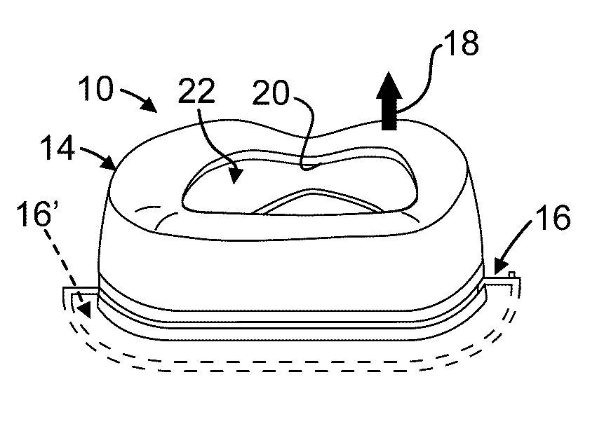
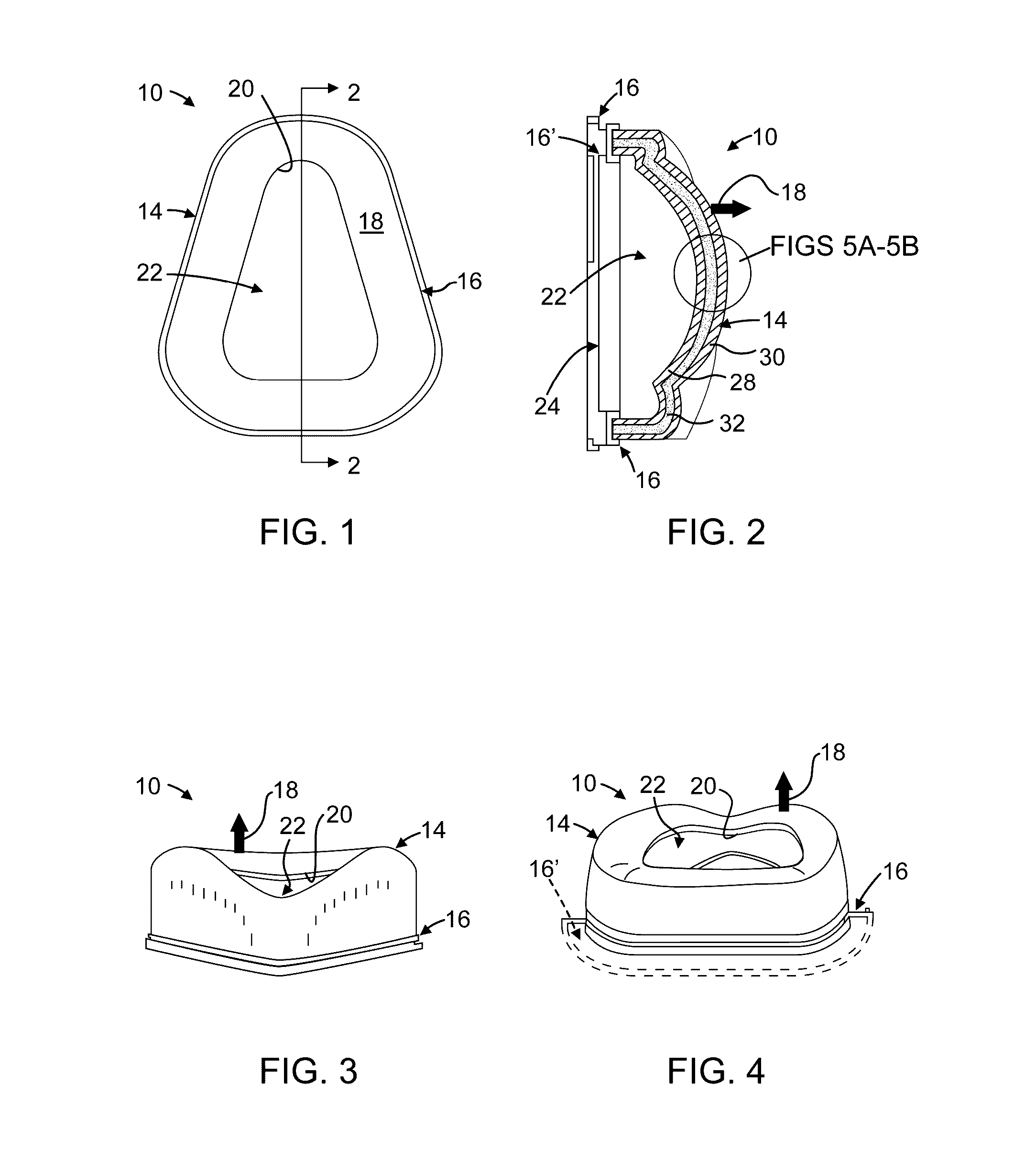
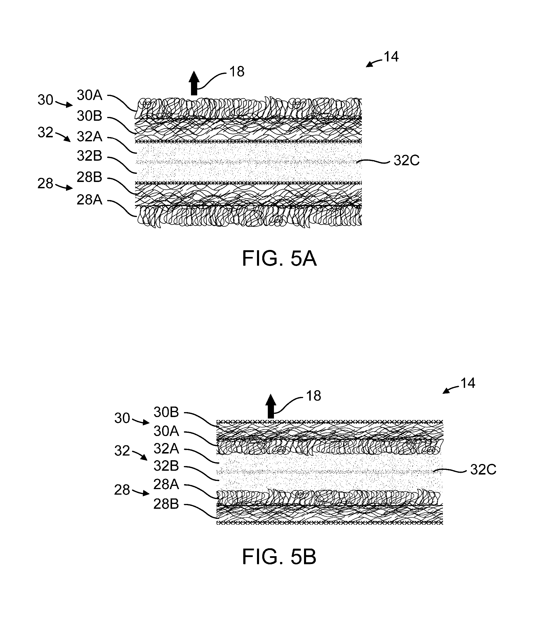
A patient interface device and cushion for the device are respectively disclosed, for preferred CPAP and BiPAP breathing masks. The cushion has a composite structure with an open rounded polygonal profile defining a mask side layer and a slip-resistant fibrous patient side layer, with an intermediate barrier layer positioned between the first and second layers. The layers are integrally bonded together into a three-dimensional conformation defining a J-shaped cross section and an inboard patient side curl opening into an air chamber juxtaposed with one or more of the patient's airways. The body exhibits flexibility between about 4 and about 10 Taber Stiffness Units. Method and apparatus for making the cushion are further described.

Description

RELATED APPLICATIONS[0001]The subject matter of this application claims priority from Applicant's prior application number PCT / US2015 / 000041, which in turn is based upon the U.S. Provisional Ser. No. 61 / 967,747; the entire contents of the afore-mentioned documents are expressly incorporated by reference herein and relied upon.TECHNICAL FIELD[0002]The current invention relates generally to breathing masks, particularly to Continuous Positive Air Pressure (CPAP) masks and to hospital respiratory masks, and more particularly, to wearer interfaces and cushions therefor.BACKGROUND[0003]Ventilation interfaces requiring a cushioned seal with the face of a patient-wearer are used for various applications. One such situation involves current treatments for obstructive sleep apnea syndrome (commonly referred to as obstructive sleep apnea, sleep apnea syndrome, and / or sleep apnea), which are referred to herein as “sleep apnea” masks. Another such situation involves administration of oxygen in ...

Claims


Application Information

Patent Timeline
IPC IPC(8): A61M16/06B29C51/32B29C51/14A61M16/00B29C51/08
CPCA61M16/0622A61M16/0666A61M16/0057B29C51/082B29C51/14B29L2031/753A61M2205/0216A61M2207/10B29K2083/00B29K2105/256B29C51/32A61M16/06A61M2205/7536A61M16/0616B29C70/345B32B5/024B32B5/026B32B5/04B32B5/22B32B5/26B32B25/042B32B25/10B32B25/20B32B3/266B32B3/28B32B2274/00B32B2307/546B32B2307/56B32B2307/7246B32B2307/7265B32B2307/744B32B2535/00
Inventor ELLIS, MICHAEL P
Owner MASK SOLUTIONS LLC
Why Eureka
Try Eureka