
Centrifugal force amplification method and system for generating vehicle lift

a technology of centrifugal force and vehicle lift, which is applied in the direction of machines/engines, cosmonautic vehicles, canard-type aircraft, etc., can solve the problems of high cost, safety problems, and efficiency, and the weight of combustible fuel is a substantial amount of overall vehicle weigh

Active Publication Date: 2017-02-23
CROWE WILLIAM R
View PDF1 Cites 8 Cited by
  • Summary
  • Abstract
  • Description
  • Claims
  • Application Information

AI Technical Summary

Benefits of technology

The present invention provides a method and system for generating air and space vehicles that are efficient, cost-effective, and safe.

Problems solved by technology

In both air and space travel, the weight of the fuel is a substantial amount of overall vehicle weight.
The requirement for so much combustible fuel presents efficiency, cost, and safety issues.

Method used


Image

  • Centrifugal force amplification method and system for generating vehicle lift
  • Centrifugal force amplification method and system for generating vehicle lift
  • Centrifugal force amplification method and system for generating vehicle lift

Examples


Embodiment Construction

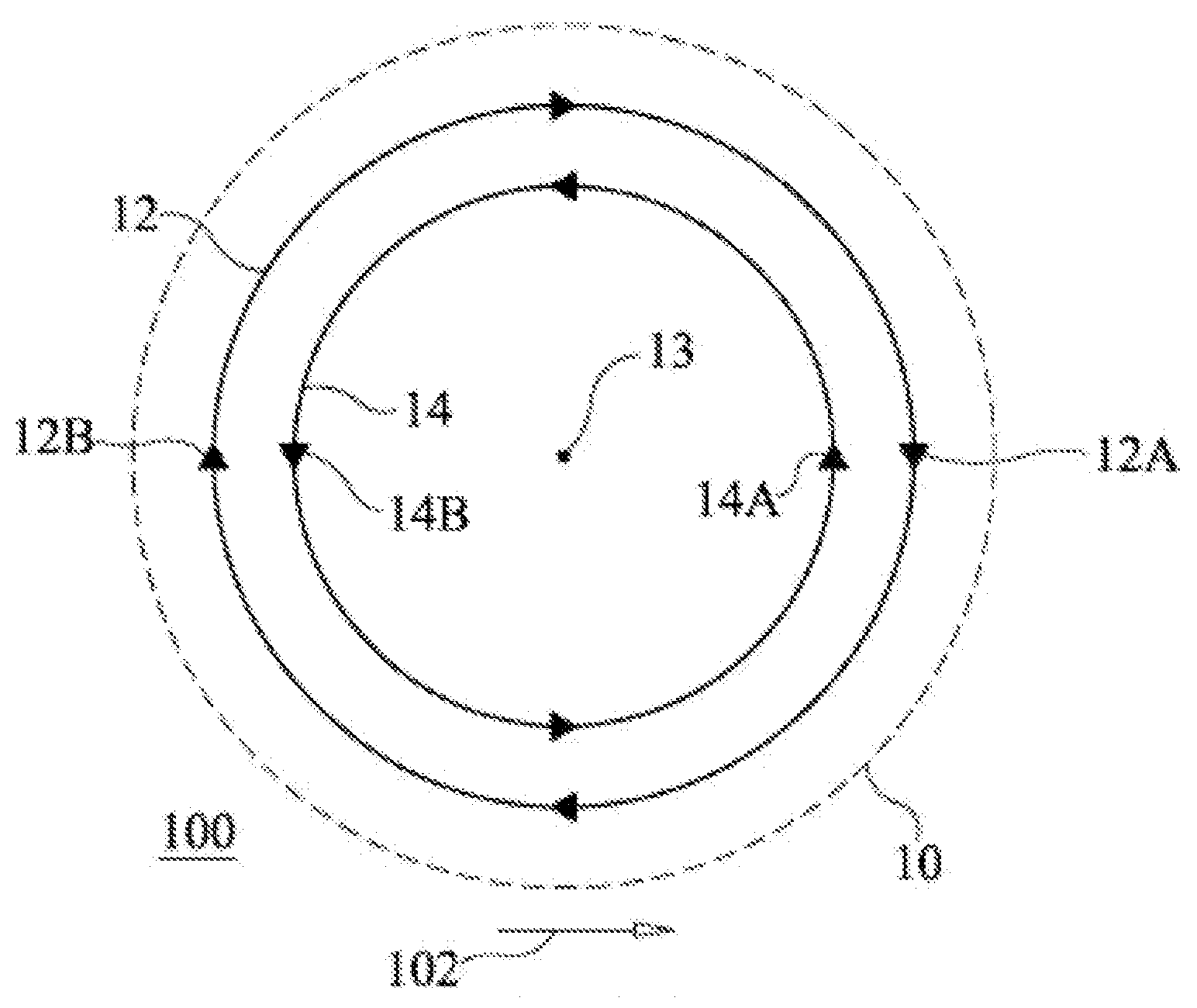
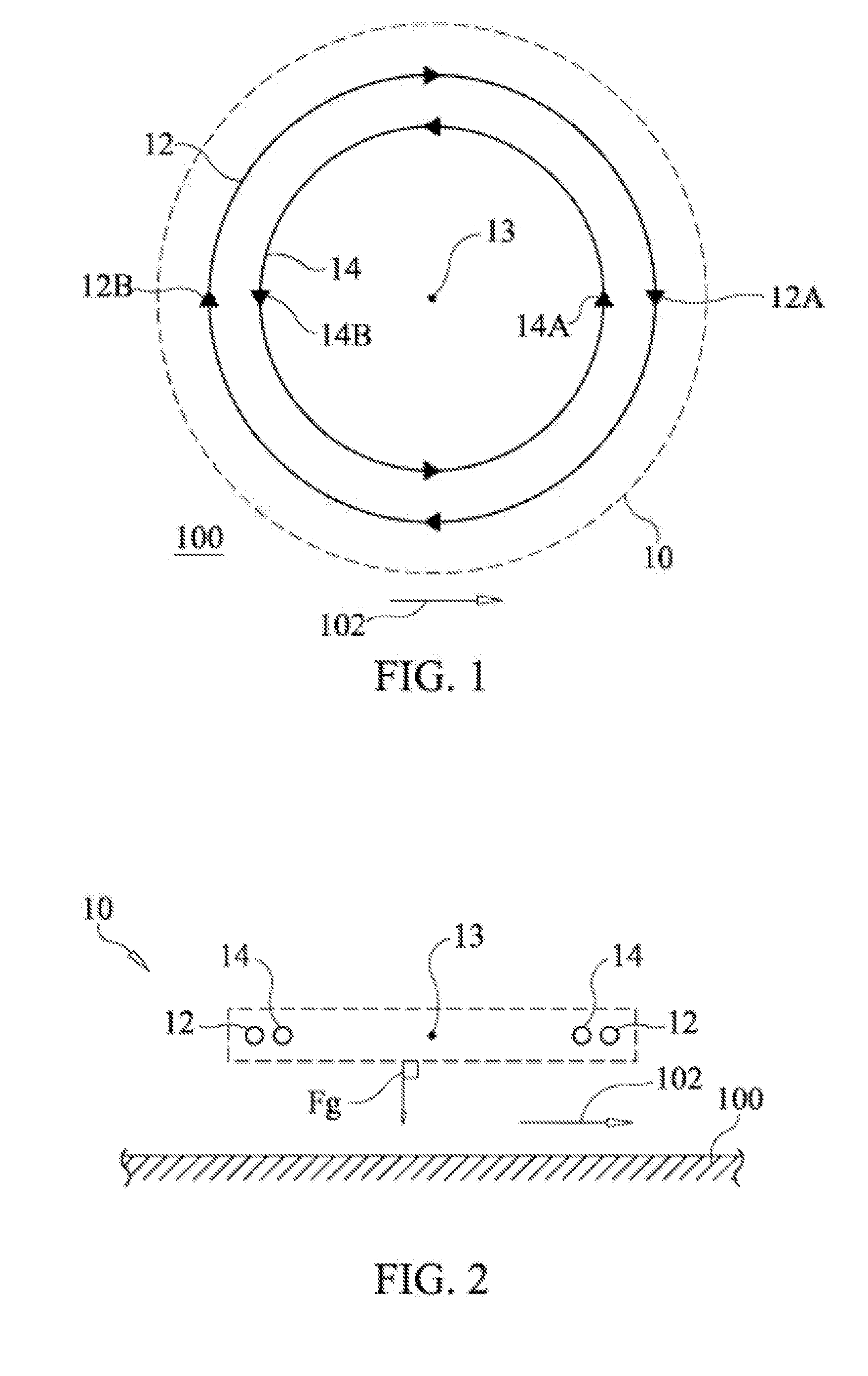
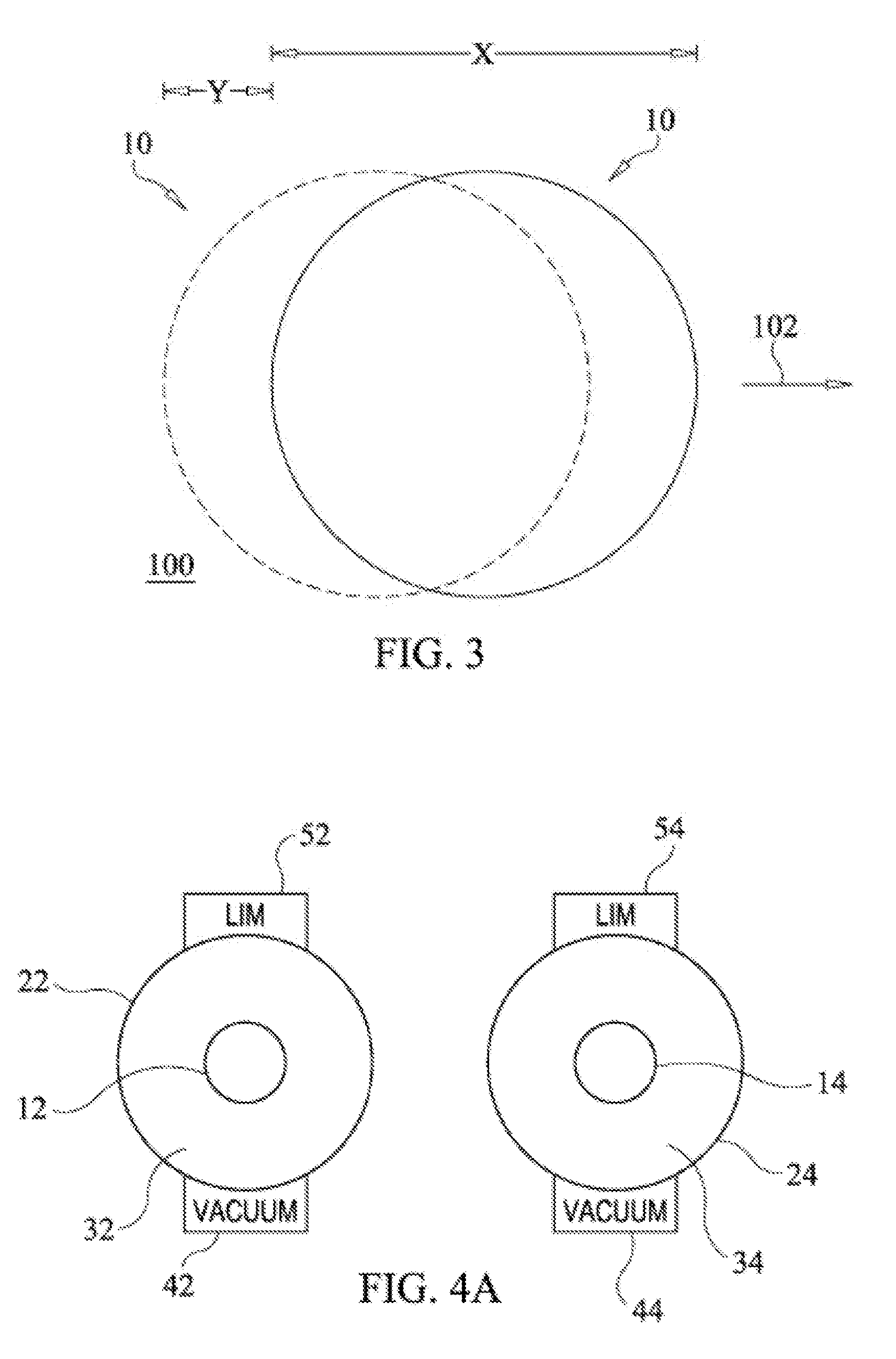
[0025]A centrifugal force amplification vehicle constructed in accordance with the present invention utilizes the motion and forces associated with counter rotating rings to generate lift for the vehicle. When the vehicle is positioned such that the vehicle's motion and forces are combined with the centrifugal force generated by a rotating planetary body (e.g., Earth, Mars, etc.), the vehicle becomes an efficient long-distance air or space vehicle having minimal or no combustible fuel requirements. As will be explained further below, the overall shape and size of the vehicle could approximate or mimic the shape / size defined by the vehicle's counter rotating rings. The vehicle could also incorporate a variety of other known aerodynamic materials and structures / systems (e.g., aerodynamic shaping, control surfaces, thrusters, etc.) without departing from the scope of the present invention. However, in order to clearly illustrate the operating principles of the present invention's centr...


PUM


Abstract

A method and system generate lift for a vehicle relative to a planetary body rotating at a rotational speed. The vehicle incorporates two concentric lift rings in a common plane. The lift rings are positioned such that their common plane is approximately perpendicular to a force of gravity on the planetary body. The hit rings are rotated M opposing directions at speeds that are at least 20 times greater than the rotational speed of the planetary body.

Description

CLAIM OF PRIORITY[0001]This application makes reference to, incorporates the same herein, claims all benefits accruing under 35 U.S.C. §120 from, and is a Continuation-in-Part of, my non-provisional application for CENTRIFUGAL FORCE AMPLIFICATION METHOD AND SYSTEM FOR GENERATING VEHICLE LIFT, earlier filed in the United States Patent and Trademark Office on 26 Aug. 2013 and there duly assigned Ser. No. 13 / 975,420 and published as U.S. 2014 / 0263846, the disclosure of which is incorporated herein in its entirety by reference, Furthermore, this application also claims benefits accruing under 35 U.S.C. §119 from my provisional application 61 / 776,916, earlier filed in the United States Patent and Trademark Office on 12 Mar. 2013, the disclosure of which is incorporated herein in its entirety by reference.BACKGROUND OF THE INVENTION[0002]Field of the Invention[0003]The invention relates generally to vehicles for long-distance air and space travel, and more particularly to a method and sys...

Claims


Application Information

Patent Timeline
Patent Type & Authority Applications(United States)
IPC IPC(8): B64G1/40B64C19/00B64C39/10B64C39/12
CPCB64G1/409B64C39/10B64C19/00B64C39/12F03H99/00
Inventor CROWE, WILLIAM R.
Owner CROWE WILLIAM R
Learn More