System and Method for Progressive Damage Monitoring and Failure Event Prediction in a Composite Structure

a composite structure and progressive damage technology, applied in the field of progressive damage monitoring and composite structure failure event prediction, can solve the problem that damaged structure often produces sound that tends to become more pronounced, and achieve the effect of accurately predicting composite failur

Active Publication Date: 2017-02-23
NAT INST AEROSPACE ASSOC +1
View PDF26 Cites 19 Cited by
  • Summary
  • Abstract
  • Description
  • Claims
  • Application Information

AI Technical Summary

Problems solved by technology

A damage-free composite structure should not return an acoustic signature, while a damaged structure often produces sound that tends to become more pronounced as the damage worsens.

Method used


Image

  • System and Method for Progressive Damage Monitoring and Failure Event Prediction in a Composite Structure
  • System and Method for Progressive Damage Monitoring and Failure Event Prediction in a Composite Structure
  • System and Method for Progressive Damage Monitoring and Failure Event Prediction in a Composite Structure

Examples


Embodiment Construction

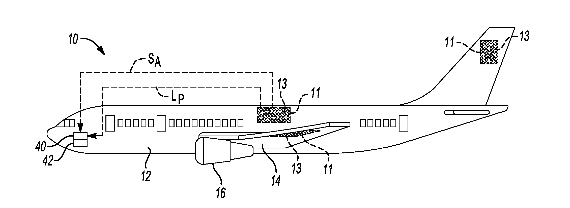
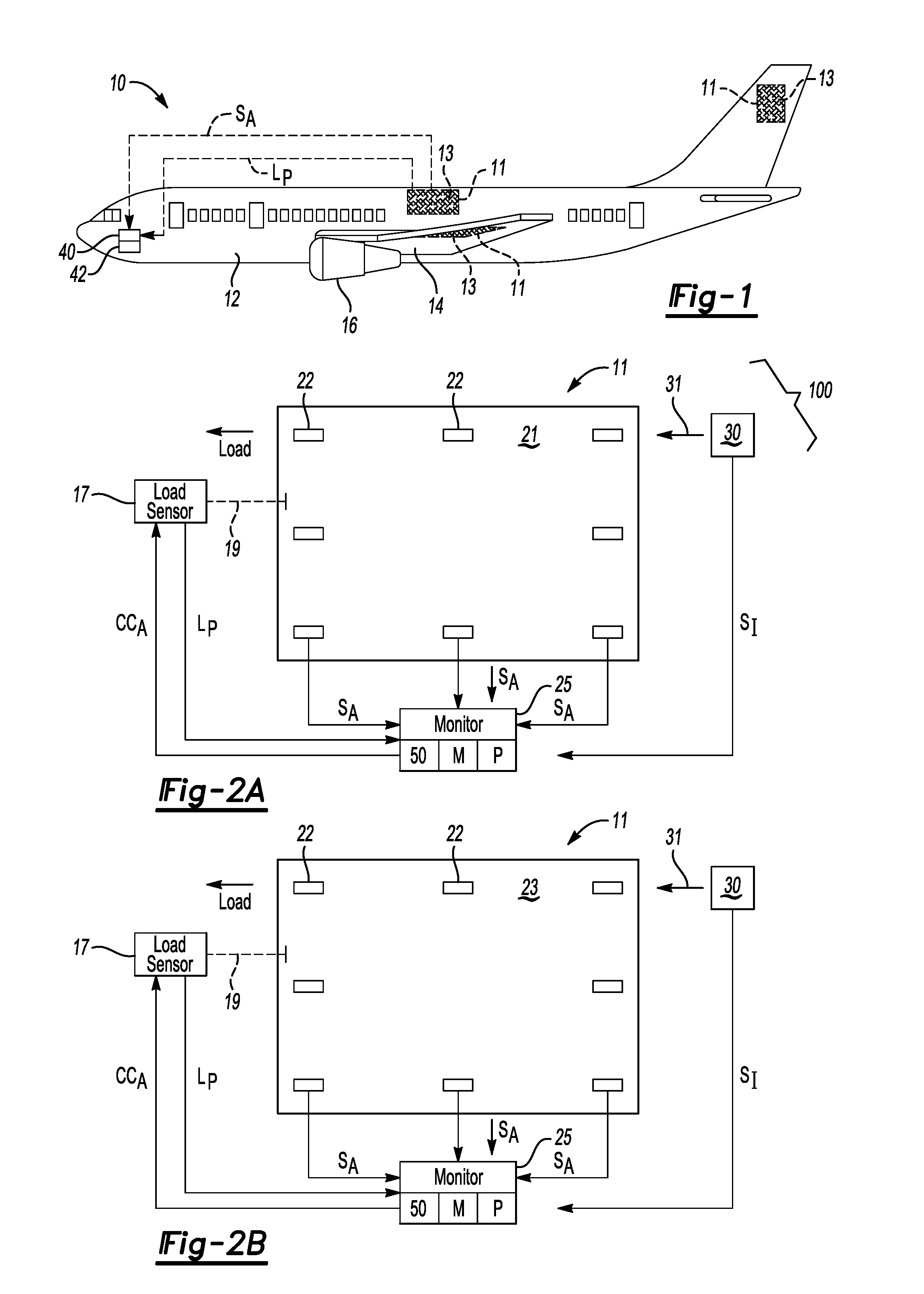
[0020]Referring to the drawings, wherein like reference numbers refer to the same or similar components in the various Figures, an example aircraft 10 is shown schematically in FIG. 1. The aircraft 10 is constructed using composite structures 11 constructed of advanced composite materials 13, e.g., one or more panels, outer skins, or other components used as part of a fuselage 12 or wings 14, or flight control surfaces, landing gear doors, fairings, stabilizers, and internal components such as floors and bulkheads, not all of which are shown in FIG. 1 but all of which are well known in the art. While the aircraft 10 is described herein as being representative of the type of structure that would benefit from use of the composite structure 11, other structural systems or components such as boats or other marine platforms, aerospace platforms, land-based or terrestrial vehicles, and stationary platforms may be contemplated within the scope of the present disclosure. For illustrative co...


PUM

PropertyMeasurementUnit
wavelengthsaaaaaaaaaa
frequencyaaaaaaaaaa

Abstract

A system for monitoring damage progression in a composite structure includes a load sensor, acoustic emission sensors, a camera, and a monitoring device. The load sensor measures an applied load to the structure. The sensors measure acoustic emission data indicative of possible damage to the structure. The camera captures image data of the structure in a designated portion of the electromagnetic spectrum. The monitoring device executes a method by which the acoustic emission data is synchronously collected with the image data and the applied load. The device automatically maps the acoustic emission data onto the image data to detect an area of damage progression in the composite structure. A failure event in the detected area of damage progression may be predicted using the mapped data, and a control action may be executed in response to the predicted failure event.

Description

CROSS-REFERENCE TO RELATED PATENT APPLICATIONS[0001]This patent application claims the benefit of and priority to U.S. Provisional Patent Application No. 62 / 207,593 filed on Aug. 20, 2015, and U.S. Provisional Patent Application No. 62 / 315,363 filed on Mar. 30, 2016, the contents of which are hereby incorporated by reference in their entirety.STATEMENT REGARDING FEDERALLY SPONSORED RESEARCH OR DEVELOPMENT[0002]The invention described herein was made in the performance of work under a NASA contract and by employees of the United States Government and is subject to the provisions of Public Law 96-517 (35 U.S.C. §202) and may be manufactured and used by or for the Government for governmental purposes without the payment of any royalties thereon or therefore. In accordance with 35 U.S.C. §202, the contractor elected not to retain title.TECHNICAL FIELD[0003]The present disclosure relates to the monitoring of damage progression and prediction of a failure event in a composite structure.BA...

Claims


Application Information

Patent Timeline
Patent Type & Authority Applications(United States)
IPC IPC(8): G01N29/14
CPCG01N29/14G01N2291/0289G01N2291/0231G01L1/00G01N21/84G01N21/8803G01N29/043G01N29/069G01N2021/8472G01N2291/0258G01N2291/106G01N2291/2694
Inventor ZALAMEDA, JOSEPH N.BURKE, ERIC R.HORNE, MICHAEL R.MADARAS, ERIC I.
Owner NAT INST AEROSPACE ASSOC
Why Eureka
Try Eureka