Light guide apparatus and virtual image display apparatus

a technology of virtual image and guide apparatus, which is applied in the direction of mirrors, instruments, optics, etc., can solve problems such as image deterioration

Active Publication Date: 2017-02-23
SEIKO EPSON CORP
View PDF2 Cites 1 Cited by
  • Summary
  • Abstract
  • Description
  • Claims
  • Application Information

AI Technical Summary

Benefits of technology

[0027]In another aspect of the invention, the video element produces color video light. In this case, the virtual image display apparatus can display a color image in a satisfactory manner.

Problems solved by technology

However, when light passes through such a Fresnel-shaped member (see FIGS. 7A to 9 of JP-T-2003-520984, for example), for example, the light is dispersed due to the difference in refractive index between the member and an air layer or between the member and another member bonded thereto, possibly resulting in image deterioration.

Method used


Image

  • Light guide apparatus and virtual image display apparatus
  • Light guide apparatus and virtual image display apparatus
  • Light guide apparatus and virtual image display apparatus

Examples


first embodiment

[0040]A light guide apparatus for a virtual image display apparatus and a virtual image display apparatus into which the light guide apparatus is incorporated according to a first embodiment of the invention will be described below with reference to the drawings.

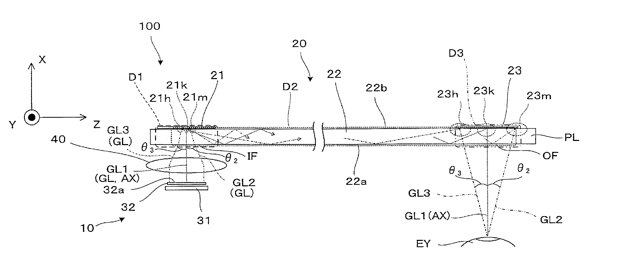
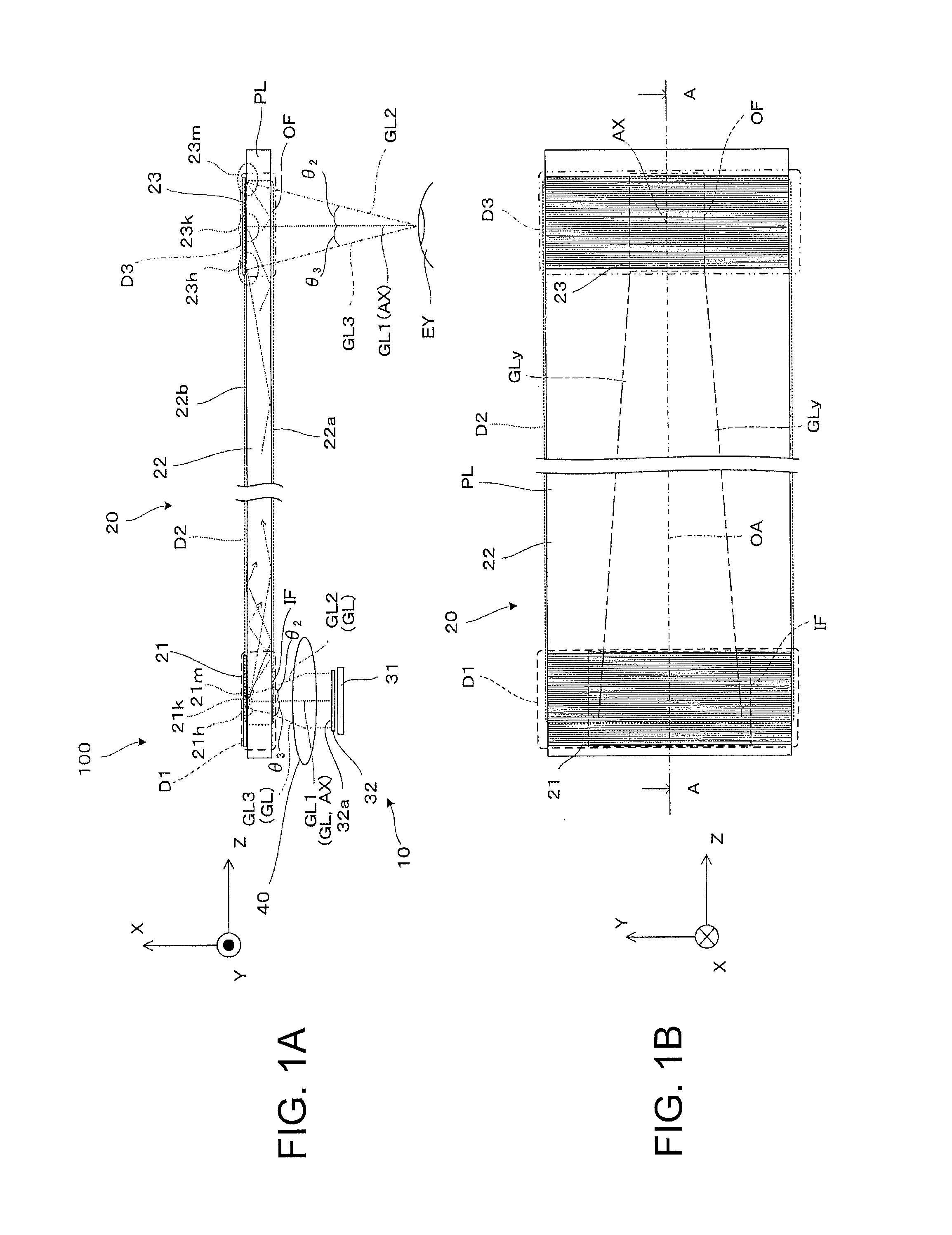
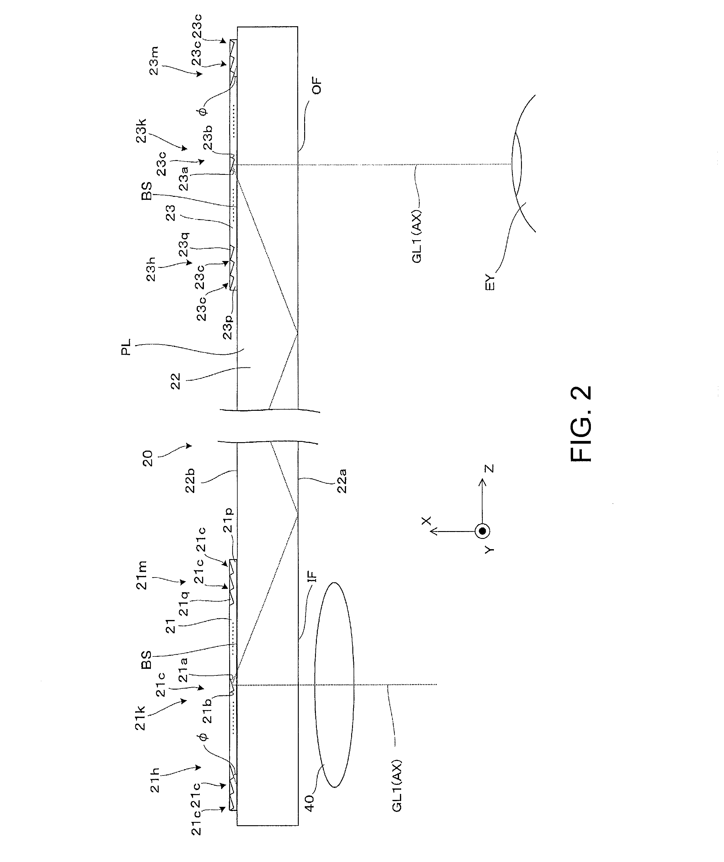
[0041]A light guide apparatus 20 incorporated into a virtual image display apparatus 100 according to the present embodiment shown in FIGS. 1A and 1B is a member for acquiring and guiding video light (image light) and outputting the video light toward a viewer and has a flat-plate-shaped exterior shape as a whole extending in one direction. The light guide apparatus 20 guides the entire video light flux in a Z direction, along which the flat plate extends. In the following description, the Z direction is called a light guide direction.

[0042]The virtual image display apparatus 100 according to the present embodiment will be described below with reference to FIG. 1A and other figures. The virtual image display apparatus 100 in...

second embodiment

[0080]A second embodiment that is a variation of the first embodiment will be described below with reference to FIG. 9. A light guide apparatus 120, which is incorporated into a virtual image display apparatus 100 according to the present embodiment, includes a dispersion elimination section 121, which is formed of one (single) prism. The structures of the light guide apparatus 120 and the virtual image display apparatus 100 excluding the dispersion elimination section 121 are the same as the structures of the light guide apparatus 20 and the virtual image display apparatus 100 shown in FIG. 1A and other figures, and the elements in the same structures will not therefore be described or otherwise explained.

[0081]In the light guide apparatus 120 according to the present embodiment, the dispersion elimination section 121 is formed of a single prism PR, which has a triangular columnar shape extending in the Y direction. More specifically, first of all, the single prism PR is made of a ...

third embodiment

[0083]A third embodiment that is a variation of the first embodiment or any other embodiment will be described below with reference to FIG. 10 and other figures. In a light guide apparatus 220 incorporated into a virtual image display apparatus 100 according to the present embodiment, each of a dispersion elimination section 221 and an image extraction section 223 has a structure in which one video light component incident on Fresnel-shaped reflection surfaces is reflected twice (multiple times), as shown in FIGS. 11A and 11E. The structures of the light guide apparatus 220 and the virtual image display apparatus 100 excluding the dispersion elimination section 221 and the image extraction section 223 are the same as the structures of the light guide apparatus 20 and the virtual image display apparatus 100 shown in FIG. 1A and other figures, and the elements in the same structures will not therefore be described or otherwise explained.

[0084]The optical paths of the video light fluxe...


PUM


Abstract

Providing an image extraction section with a plurality of video light reflection surfaces that are Fresnel-shaped reflection surfaces allows reduction in the thickness of a light guide apparatus and hence the thickness and size of a virtual image display apparatus. In particular, providing a dispersion elimination section for eliminating wavelength dispersion in correspondence with the image extraction section suppresses image deterioration resulting from dispersion (chromatic aberrations) on a wavelength band basis.

Description

BACKGROUND[0001]1. Technical Field[0002]The present invention relates to a light guide apparatus that can be used in a virtual image display apparatus that presents a viewer with video images formed, for example, by an image display apparatus and further relates to a virtual image display apparatus using the light guide apparatus.[0003]2. Related Art[0004]A variety of optical systems have been proposed as a video light guiding optical system incorporated into a virtual image display apparatus, such as a head mounted display (hereinafter also referred to as HMD) mounted on a viewer's head (see JP-T-2003-520984, the term “JP-T” as used herein means a published Japanese translation of a PCT patent application).[0005]As a virtual image display apparatus of this type or a light guide apparatus suitable for the virtual image display apparatus, for example, there is a known apparatus using a reflection member having the shape of a Fresnel lens (the shape is hereinafter referred to as a Fre...

Claims


Application Information

Patent Timeline
Patent Type & Authority Applications(United States)
IPC IPC(8): G02B27/01G02B27/30F21V8/00G02B5/09G02B17/00
CPCG02B27/0172G02B5/09G02B17/006G02B2027/0116G02B6/0031G02B6/0053G02B27/30G02B6/0055G02B3/08G02B6/29328G02B6/29394G02B17/008
Inventor TAKEDA, TAKASHITOTANI, TAKAHIROTAKAGI, MASAYUKIMIYAO, TOSHIAKIKOMATSU, AKIRA
Owner SEIKO EPSON CORP
Why Eureka
Try Eureka