Image-processing device, image-capturing device, image-processing method, and storage medium
- Summary
- Abstract
- Description
- Claims
- Application Information
AI Technical Summary
Benefits of technology
Problems solved by technology
Method used
Image
Examples
first exemplary embodiment
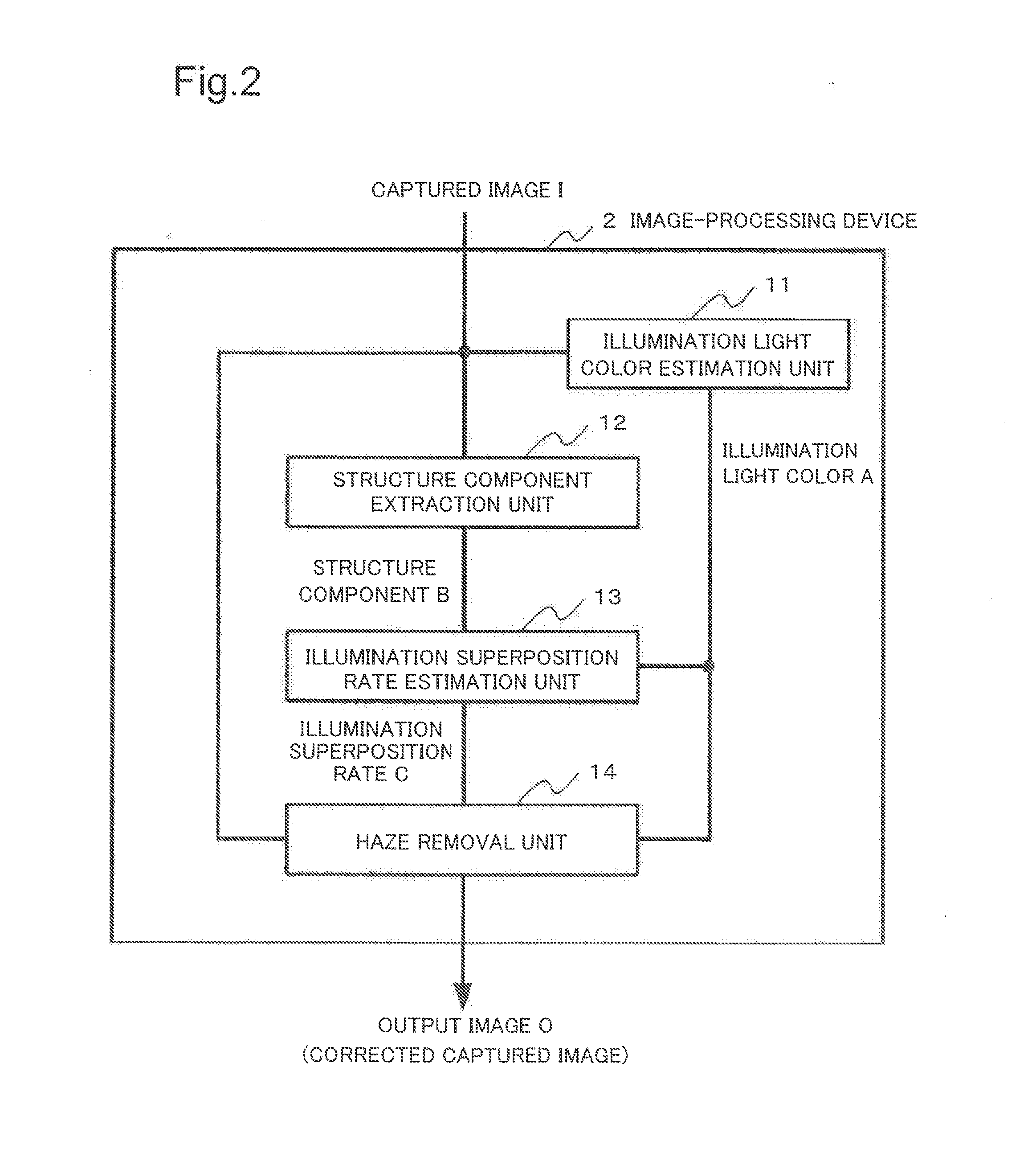
[0033]First, an image-capturing device 4 according to a first exemplary embodiment of the present invention will be described.
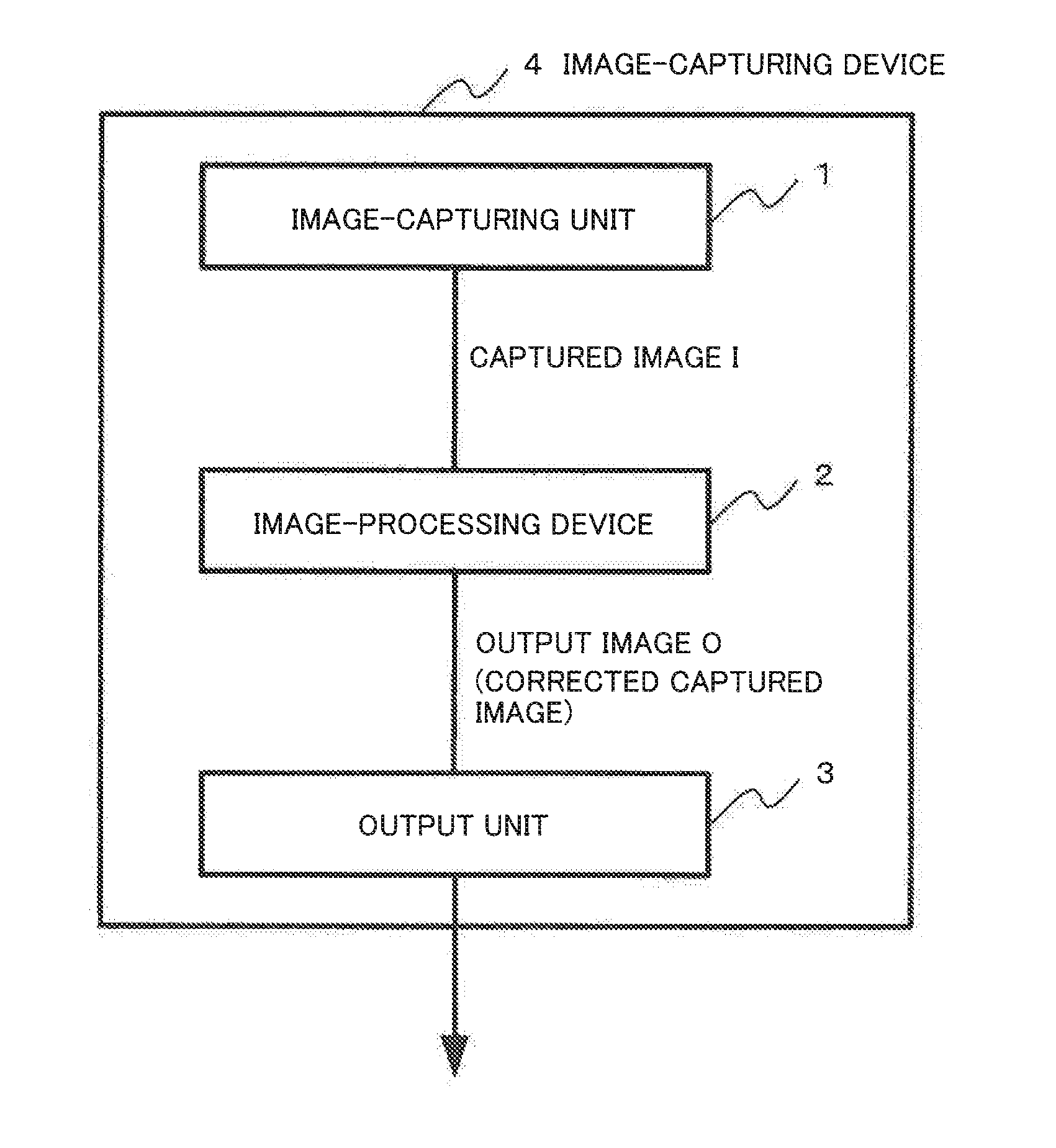
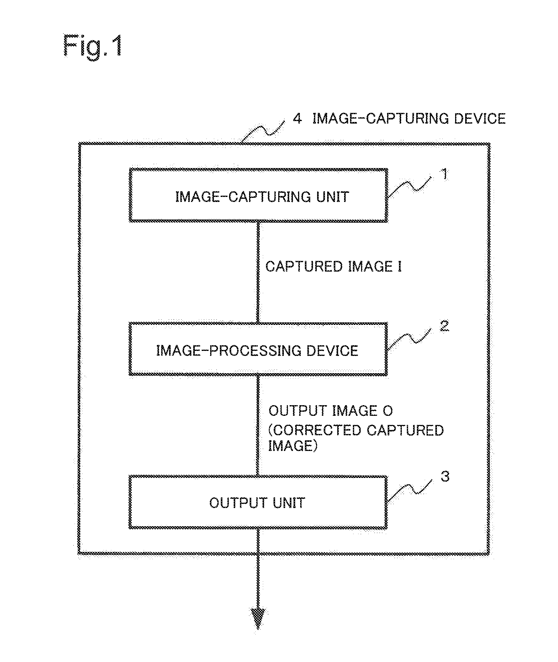
[0034]FIG. 1 is a block diagram showing an example of a configuration of the image-capturing device 4 according to the first exemplary embodiment of the present invention.
[0035]The image-capturing device 4 according to the first exemplary embodiment includes an image-capturing unit 1, an image-processing device 2, and an output unit 3.
[0036]The image-capturing unit 1 captures a captured image (I(x,λ)) of an object to be imaged. The image-capturing unit 1 is constituted, for example, so as to include an image sensor using a Charge Coupled Device (CCD) or a Complementary Metal Oxide Semiconductor (CMOS). The image-capturing unit 1 may receive the captured image of the object from image-capturing equipment which is not shown in the drawing. Therefore, the image-capturing unit 1 is also called a reception unit. Since the captured image I(x,λ) is generated based o...
second exemplary embodiment
[0058]A second exemplary embodiment will be described.
[0059]FIG. 4 is a block diagram showing an example of an image-processing device 2 according to the second exemplary embodiment of the present invention.
[0060]The image-processing device 2 according to the second exemplary embodiment includes the illumination light color estimation unit 11, the structure component extraction unit 12, the illumination superposition rate estimation unit 13, the haze removal unit 14, and an exposure correction unit 15. As mentioned above, the image-processing device 2 according to the second exemplary embodiment is different from the image-processing device 2 according to the first exemplary embodiment in a point including the exposure correction unit 15. Other components of the image-processing device 2 according to the second exemplary embodiment are similar as those of the image-processing device 2 according to the first exemplary embodiment respectively. Furthermore, the image-capturing unit 1 a...
third exemplary embodiment
[0066]A third exemplary embodiment will be described.
[0067]FIG. 5 is a block diagram showing an example of a configuration of an image-processing device 2 according to the third exemplary embodiment.
[0068]The image-processing device 2 according to the third exemplary embodiment includes the illumination light color estimation unit 11, the structure component extraction unit 12, the illumination superposition rate estimation unit 13, a haze removal unit 14′, an exposure correction unit 15′, a texture component calculation unit 16, and a texture component modification unit 17.
[0069]As mentioned above, the image-processing device 2 according to the third exemplary embodiment is different from the image-processing device 2 according to the second exemplary embodiment in a point that including the texture component calculation unit 16 and the texture component modification unit 17. Furthermore, the image-processing device 2 according to the third exemplary embodiment is different in a po...
PUM
 Abstract
Description
Claims
Application Information
 - R&D
- Intellectual Property
- Life Sciences
- Materials
- Tech Scout
- Unparalleled Data Quality
- Higher Quality Content
- 60% Fewer Hallucinations
Browse by: Latest US Patents, China's latest patents, Technical Efficacy Thesaurus, Application Domain, Technology Topic, Popular Technical Reports.
© 2025 PatSnap. All rights reserved.Legal|Privacy policy|Modern Slavery Act Transparency Statement|Sitemap|About US| Contact US: help@patsnap.com


