Stator positioner for electrostatic generator electrodes and new electrode design

Active Publication Date: 2017-02-23
LAWRENCE LIVERMORE NAT SECURITY LLC
View PDF11 Cites 10 Cited by
  • Summary
  • Abstract
  • Description
  • Claims
  • Application Information

AI Technical Summary

Benefits of technology

[0009]The problem addressed by this invention is one that is important to solve in designing the stator and rotor electrode systems of E-S generator / motors when the rotor electrodes are attached to the rotor. The problem is how to compensate for the expansion and contraction of the radius of the rotor (owing to centrifugal force) of an EMS that occurs as it is charged or discharged. A simple mechanically-based system has been described for controlling the rotor / stator electrode spacing in an electrostatic motor / generator system the rotor electrodes of which are mounted on the outer or inner surface of the rotor of the EMB. The positioning system acts through the use of the repelling force between a ring of permanent magnets on the rotor and stationary permanent magnets pushing on spring-loaded lever arms. These arms are coupled through the use of a rail-guided “cart” to azimuthally segmented stator electrode arrays. It is also shown that the system can be designed so that it also can compensate for the variation of power output with speed that is common to generators, either electrostatic or electromagnetic. Finally, an improved version of the stator electrode structure involving tailoring the thickness and gaps of dielectric inserts is described. This new form of stator design can result in major gains in the output of the E-S generator relative to the older design.

Problems solved by technology

The problem is how to compensate for the expansion and contraction of the radius of the rotor (owing to centrifugal force) of an EMS that occurs as it is charged or discharged.

Method used


Image

  • Stator positioner for electrostatic generator electrodes and new electrode design
  • Stator positioner for electrostatic generator electrodes and new electrode design
  • Stator positioner for electrostatic generator electrodes and new electrode design

Examples


Embodiment Construction

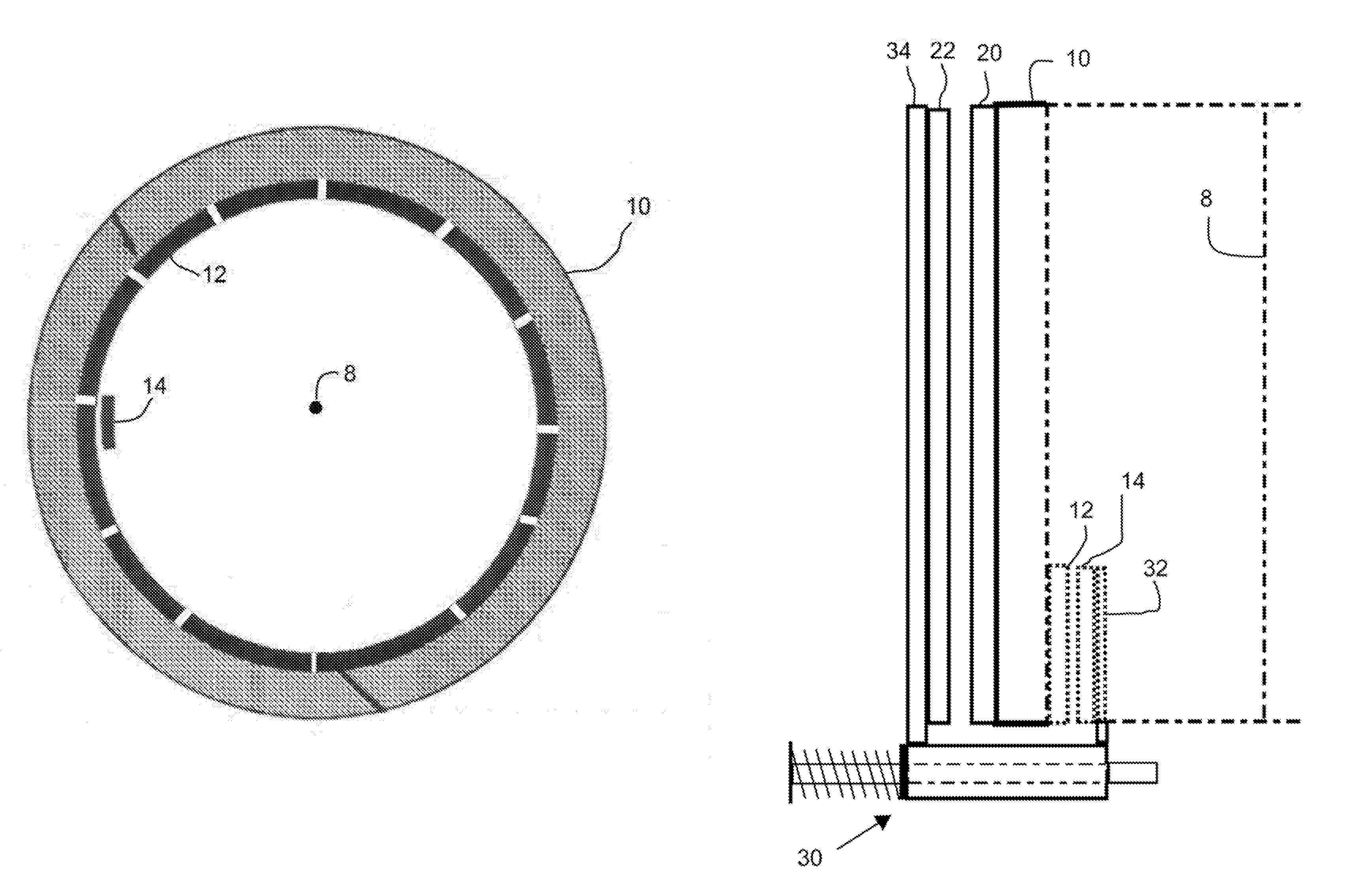
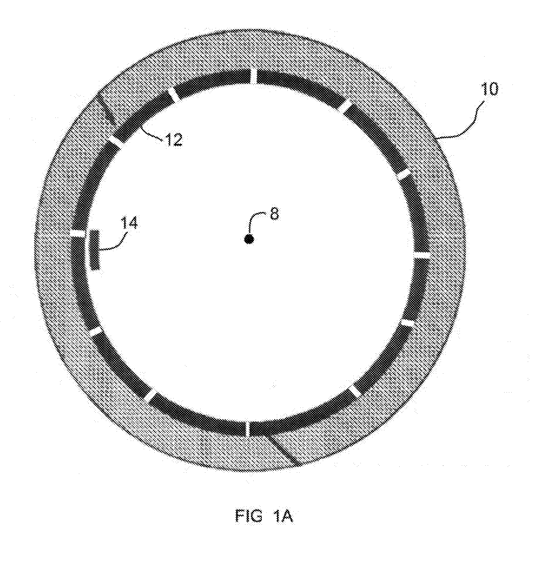
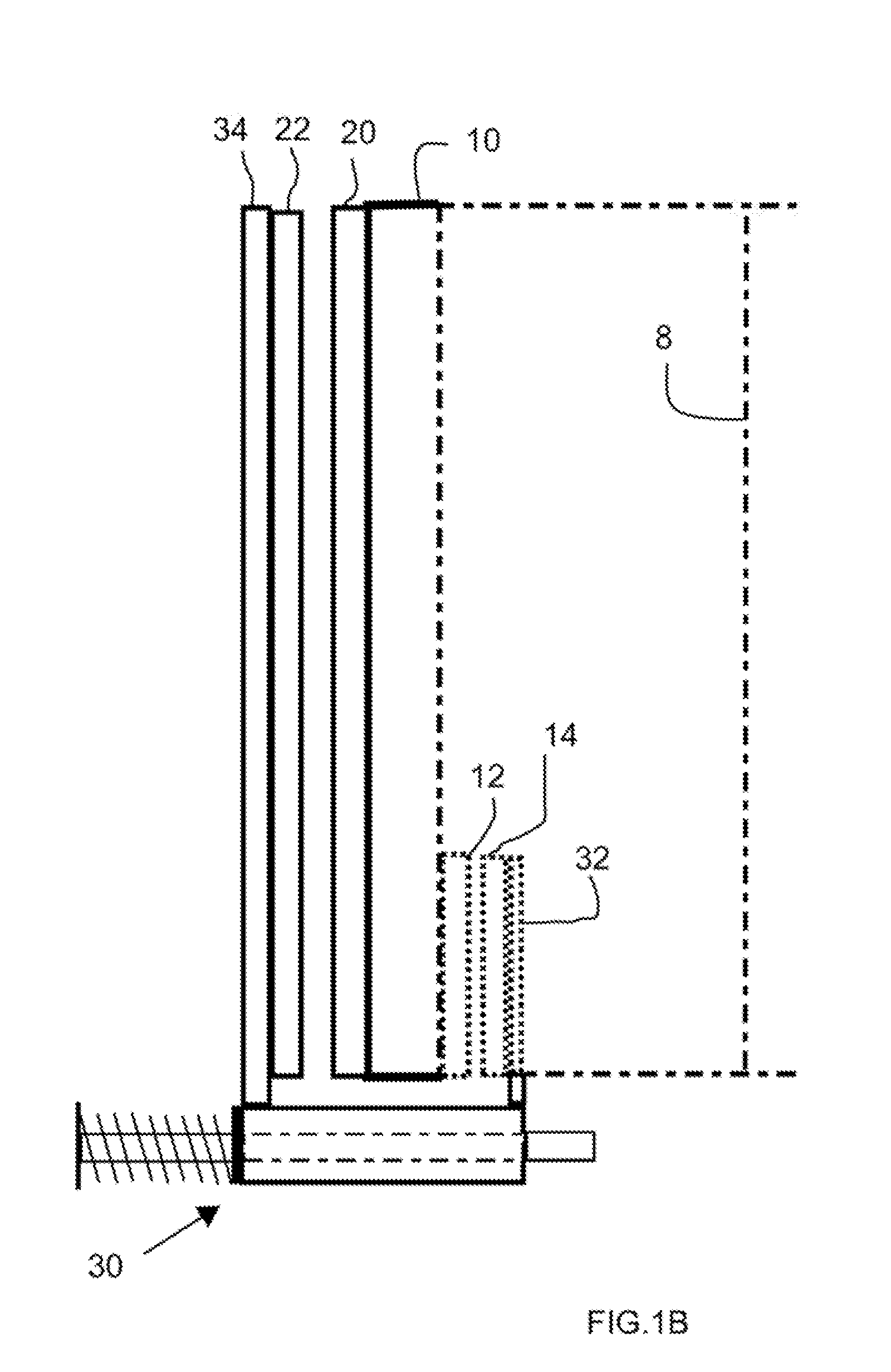
[0021]This invention solves a problem that is associated with the use of an electrostatic generator / motor in an electromagnetic battery (EMB) / flywheel energy storage device. When charged from a low speed, the rotor of the EMB expands because of centrifugal forces. In a large EMB, this expansion can be of order 2 centimeters or more. If the rotor electrodes are mounted on the outer or inner surface of the rotor, this expansion can change the rotor / stator gap by an unacceptably large amount. This invention employs a mechanical means for moving the stator electrodes so as to maintain a constant gap. Although it is possible to attached electrical to the mechanical means, they do not contribute to the mechanical operation of the invention. For example, electrical elements could be attached to the mechanical means to electrically monitor the expansion or contraction of the rotor as well as to monitor the gap, but in the present invention, such electrical elements are not part of the mecha...


PUM


Abstract

A mechanical system is provided for maintaining a desired gap between a stator electrode array and a rotor electrode array by employing repelling magnets on the inner surface of the rotor and on movable carts that support azimuthally segmented stator arrays.

Description

CROSS-REFERENCE TO RELATED APPLICATION[0001]This application claims the benefit of U.S. Provisional Patent Application No. 62 / 207,877 titled “Stator Positioner for Electrostatic Generator Electrodes and New Electrode Design,” filed Aug. 20, 2015, incorporated herein by reference.STATEMENT REGARDING FEDERALLY SPONSORED RESEARCH OR DEVELOPMENT[0002]The United States Government has rights in this invention pursuant to Contract No. DE-AC52-07NA27344 between the U.S. Department of Energy and Lawrence Livermore National Security, LLC, for the operation of Lawrence Livermore National Laboratory.BACKGROUND OF THE INVENTION[0003]Field of the Invention[0004]The present invention relates to a problem associated with the use of an electrostatic generator mounted on a spinning rotor that is subject to radial growth associated with centrifugal force acting on the rotor, and more specifically, it relates to a simple mechanical system for maintaining the gap between the stator electrode array and t...

Claims


Application Information

Patent Timeline
Patent Type & Authority Applications(United States)
IPC IPC(8): H02N1/00
CPCH02N1/00H02N1/08
Inventor POST, RICHARD F.
Owner LAWRENCE LIVERMORE NAT SECURITY LLC
Why Eureka
Try Eureka