Electrostatic atomizing coating apparatus and coating method

a technology of atomizing coating apparatus and coating method, which is applied in the direction of electrostatic spraying apparatus, coating, induction-charge spraying, etc., can solve the problems of paint not being able to efficiently apply paint to the coating target, paint cannot be atomized sufficiently to a particle diameter suitable for the application, etc., to achieve the effect of improving coating efficiency

Active Publication Date: 2017-03-02
TOYOTA JIDOSHA KK
View PDF12 Cites 14 Cited by
  • Summary
  • Abstract
  • Description
  • Claims
  • Application Information

AI Technical Summary

Benefits of technology

[0018]electrostatically atomizing the thread-shaped paint discharged from the open end by forming an electrostatic field between the open end and a coating target, and adjusting an intensity of the electrostatic field to control a particle diameter of the electrostatically atomized thread-shaped paint. This makes it possible to atomize the paint to a particle suitable for the application without using shaping air. Hereby, paint particles attached to...

Problems solved by technology

However, in the rotary atomizing coating apparatus, an accompanied flow of the shaping air is returned back by a coating target to raise up coating particles, which may cause such a possibility that coating efficiency decreases.
However, even if the rotation speed of the rotary head is...

Method used


Image

  • Electrostatic atomizing coating apparatus and coating method
  • Electrostatic atomizing coating apparatus and coating method
  • Electrostatic atomizing coating apparatus and coating method

Examples


embodiment 2

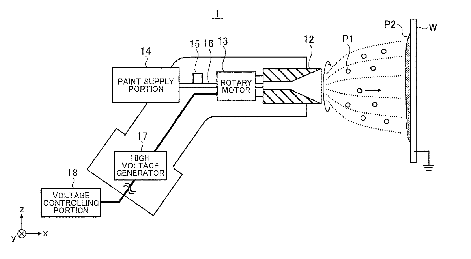
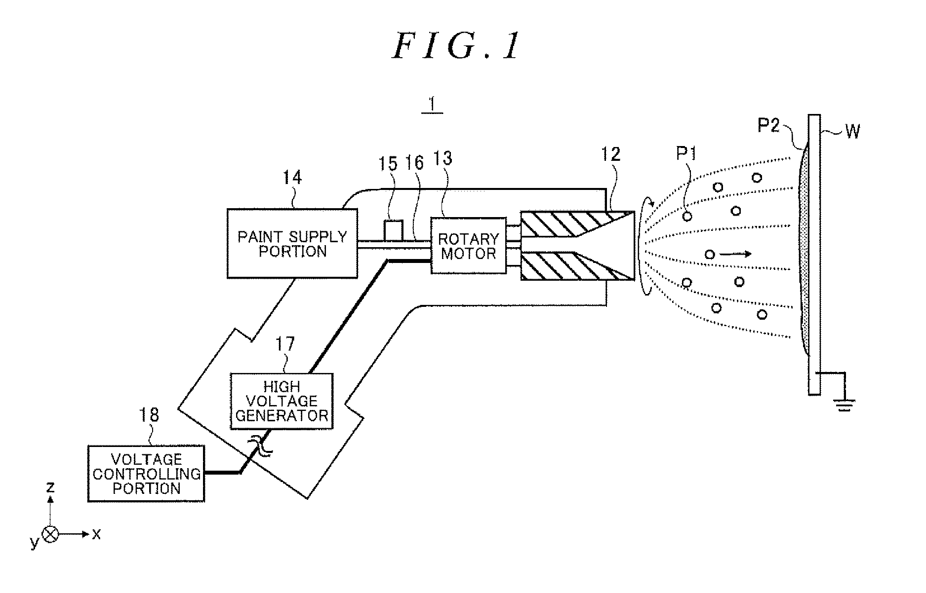
[0079]FIG. 11 is a sectional view schematically illustrating an electrostatic atomizing coating apparatus 2 according to The electrostatic atomizing coating apparatus 2 further includes an outer ring 19 in comparison with the electrostatic atomizing coating apparatus 1. Note that an xyz right handed coordinate system is illustrated in FIG. 11 for convenience of description of a positional relationship among constituents.

[0080]As illustrated in FIG. 11, the outer ring 19 is used as a supporting electrode of a rotary head 12 as a negative electrode, and has a circular column shape formed so as to surround an outer peripheral surface of the rotary head 12.

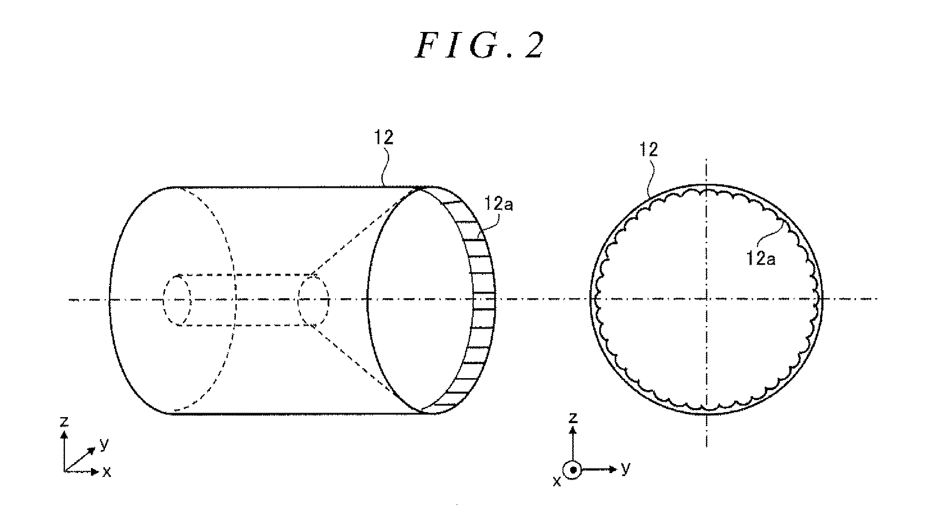
[0081]FIG. 12 is a perspective view and a side view of the outer ring 19. Note that an xyz coordinate in FIG. 12 is the same coordinate as in FIG. 11. The outer ring 19 has a circular column shape formed so as to surround the outer peripheral surface of the rotary head 12 as described above. Further, the outer ring 19 includes an inc...

embodiment 3

[0095]FIG. 18 is a sectional view schematically illustrating an electrostatic atomizing coating apparatus 3 according to As compared with the electrostatic atomizing coating apparatus 2, the electrostatic atomizing coating apparatus 3 includes a plurality of rotary heads 12 placed in parallel with each other, instead of a single rotary head 12. Further, a plurality of rotary motors 13 is provided to the plurality of rotary heads 12, respectively.

[0096]With the use of the plurality of rotary heads 12, the electrostatic atomizing coating apparatus 3 can improve a degree of freedom of a coating pattern and machining ability. The other configurations of the electrostatic atomizing coating apparatus 3 are the same as those of the electrostatic atomizing coating apparatus 2, so descriptions thereof are omitted.

[0097]As described above, the electrostatic atomizing coating apparatuses according to Embodiments 1 to 3 electrostatically atomize the paint P1 to a particle diameter suitable for...


PUM


Abstract

An electrostatic atomizing coating apparatus and method incorporate a rotary head having a base portion, an open end and a plurality of grooves formed radially on an inner peripheral surface of the open end, an inside diameter of the rotary head increasing from the base portion toward the open end, and a motor configured to rotate the rotary head to discharge a thread-shaped paint. A voltage is applied to the rotary head so as to form an electrostatic field between the open end of the rotary head and an earthed coating target and to electrostatically atomize the thread-shaped paint discharged from the open end. Voltage output from the generator is controlled so as to adjust an intensity of the electrostatic field and to control a particle diameter of the electrostatically atomized thread-shaped paint.

Description

INCORPORATION BY REFERENCE[0001]The disclosure of Japanese Patent Application No. 2015-169455 filed on Aug. 28, 2015 including the specification, drawings and abstract is incorporated herein by reference in its entirety.BACKGROUND1. Technical Field[0002]This application relates to an electrostatic atomizing coating apparatus and a coating method thereof.2. Description of Related Art[0003]A general rotary atomizing coating apparatus sprays shaping air on a thread-shaped water-based paint discharged from a bell-shaped rotary head that rotates at a high speed, so as to atomize the thread-shaped water-based paint and to control a coating pattern. However, in the rotary atomizing coating apparatus, an accompanied flow of the shaping air is returned back by a coating target to raise up coating particles, which may cause such a possibility that coating efficiency decreases.[0004]A solution to such a possibility is disclosed in Japanese Patent Application Publication No. 8-108106 (JP 8-1081...

Claims


Application Information

Patent Timeline
IPC IPC(8): B05B5/04B05D1/04B05B5/00
CPCB05B5/0415B05D1/04B05B5/0407B05B5/005B05B5/006B05B5/081B05D1/06B05B5/0426B05B5/0411B05B5/0533B05B5/043B05B5/0418B05C11/1018B05C19/04B05C19/008
Inventor TANI, SHINJINABESHIMA, ASTUOKONDO, TAKAHITO
Owner TOYOTA JIDOSHA KK
Why Eureka
Try Eureka