Device for detecting dislogded anchoring apparatus and the like

a technology for disconnection and anchorage, applied in the direction of illuminating signalling devices, vessel construction, transportation and packaging, etc., can solve the problems of inability to determine whether secure anchorage occurs, drift is unacceptable, etc., and achieve the effect of reducing buoyancy

Inactive Publication Date: 2017-03-02
SHUMATE RODNEY SCOTT +1
View PDF12 Cites 5 Cited by
  • Summary
  • Abstract
  • Description
  • Claims
  • Application Information

AI Technical Summary

Benefits of technology

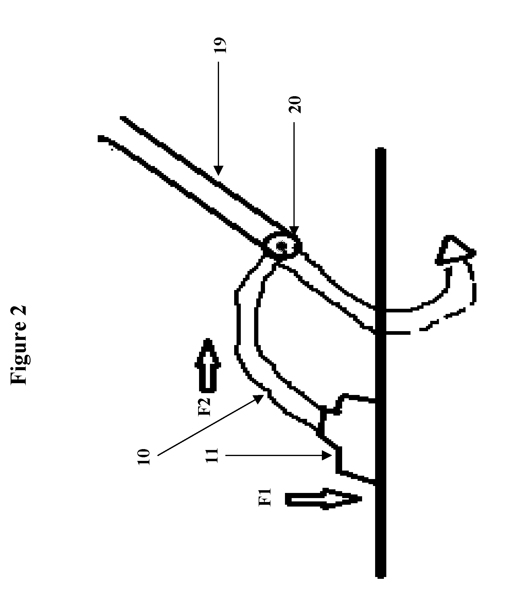
[0044]The weight allows the triggered anchor alarm to sit adjacent to the anchor until anchor displacement and creates the tension required to displace sensors in the housing component.
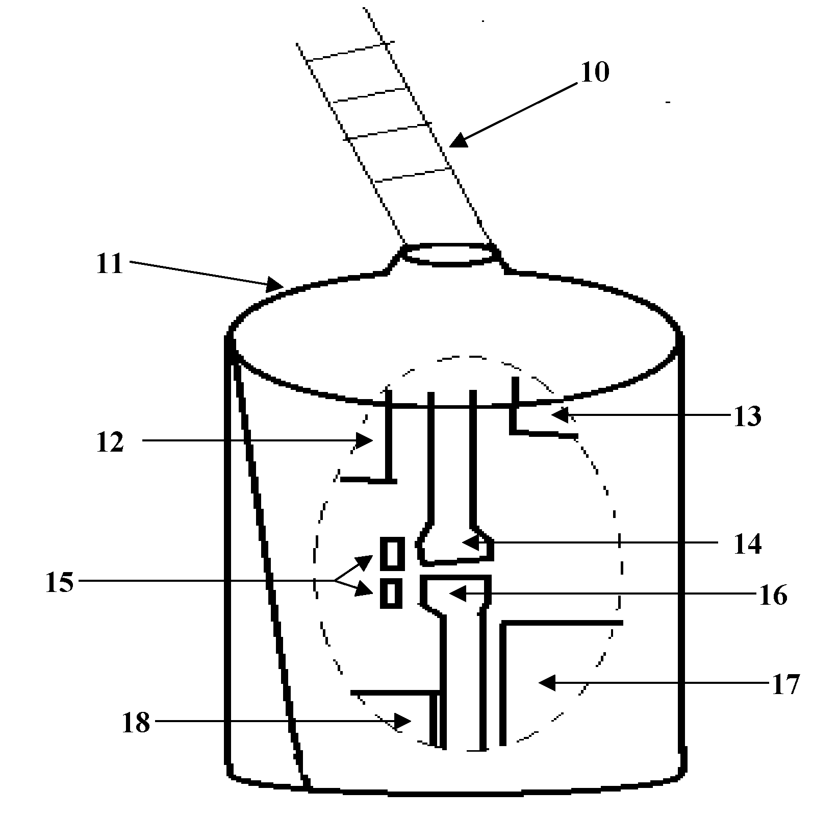
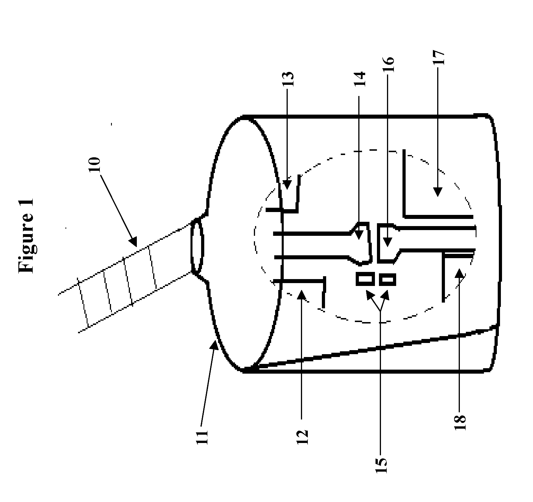
[0045]The invention further provides an anchor alarm system for maritime ships comprising: (a) a secondary rode; (b) a housing attached to said secondary rode; said housing including: (i) electronic circuitry that controls timing for deployment, setting, redeployment and information gathering from other devices; (ii) a signal generating device which is activated by said electronic circuitry; (iii) one or more latching mechanisms; (iv) sensing devices attached to said latching mechanism; (v) a battery module; and (vi) means for reducing buoyancy and (c) one or multiple water-level receivers which can alert the user of the anchor status by means of visual, kinetic, or audible stimulus.

Problems solved by technology

The prior art has largely concerned itself with the problem of locating and retrieving anchors; however, an unaddressed problem is that of determining whether secure anchorage occurs.
In areas near dangerously shallow bottoms, submerged rocks, the shoreline, other vessels, or mooring or fishing lines, this drift is unacceptable.

Method used


Image

  • Device for detecting dislogded anchoring apparatus and the like
  • Device for detecting dislogded anchoring apparatus and the like
  • Device for detecting dislogded anchoring apparatus and the like

Examples


Embodiment Construction

[0049]The problematic nature of anchors for floating objects will first be described using the example of an anchored ship. To anchor, a ship lowers an anchor hanging on an anchor chain or hawser onto the waterway bottom so that the anchor, as well as also a large portion of the anchor chain / hawser lies on the sea bottom. What is important here is that the fixation of the ship at a certain area is not affected through the anchor connecting with the sea floor, but rather through the weight imposed on the portion of the anchor chain / hawser lying on the sea floor.

[0050]An anchored ship thus can, within a certain given range, move freely about the leverage point of the anchor chain on the sea bottom biasing the ship, thereby allowing for some give against external forces acting on the ship, as for example the force of currents or winds. As the amount of such external forces acting on the ship increase, this may led to the reaching of a particular condition, dependent upon a value based ...


PUM


Abstract

The present invention provides an anchor alarm device which is a manually deployed weighted device attached to or near the anchor which signals to device equipment at water-level. The device detects the movement of, or physical force generated by, a dislodged anchor. When deployed, a component of the anchor alarm device rests adjacent to or as part of a seated anchor at a distance predetermined by the tolerance of the secondary rode. The secondary rode connects the device directly to the anchor, or near the anchor on the primary rode. Upon displacement of the set anchor, in excess of the secondary rode, the device alerts the user. The device utilizes sensor monitoring inside of a housing component to detect a force indicative of anchor displacement. This detection triggers a signals emission which alerts the user of the change in position. In cases wherein the anchor is not immediately retrieved, device re-arms autonomously and stops emission of the alarm signal until the next anchor displacement. The system communicates with signal devices on board or deployed near the anchoring vessel in order to alert the user.

Description

[0001]This application claims the priority benefit under 35 U.S.C. section 119 of U.S. Provisional Patent Application No. 62 / 211,821 entitled “Triggered Anchor Alarm” filed on Aug. 30, 2015, and which is in its entirety herein incorporated by reference.FIELD OF THE INVENTION[0002]The instant invention relates to an anchoring alarm, especially for boats. The present invention further relates to an anchor and anchor chain trigger alarm device for anchored floating objects, in particular ships and leisure boats. The invention additionally relates in general to ship anchoring systems and in particular to a system for monitoring performance of a ship's anchoring system and for producing usable data and alarms when the anchoring system fails.[0003]This invention further relates generally to alarm systems and more particularly to an apparatus for indicating movement of a boat relative to a given position where it may be moored or otherwise secured. Although the invention will be described ...

Claims


Application Information

Patent Timeline
Patent Type & Authority Applications(United States)
IPC IPC(8): B63B45/00B63B21/24
CPCB63B45/00B63B2201/04B63B2201/02B63B21/24B63B21/02B63B2021/008
Inventor SHUMATE, RODNEY SCOTTHAMPL, STEVEN
Owner SHUMATE RODNEY SCOTT
Why Eureka
Try Eureka