Sensor Arrangements, Sensor Systems, and Methods for Determining Height of Liquids in Tanks

a technology of sensors and liquids, applied in the direction of instruments, machines/engines, using reradiation, etc., can solve the problems of inability to provide very good accuracy or resolution, inconvenient use for normal consumers, and inaccuracy, reliability or cos

Active Publication Date: 2017-03-02
MOPEKA PROD LLC
View PDF6 Cites 13 Cited by
  • Summary
  • Abstract
  • Description
  • Claims
  • Application Information

AI Technical Summary

Benefits of technology

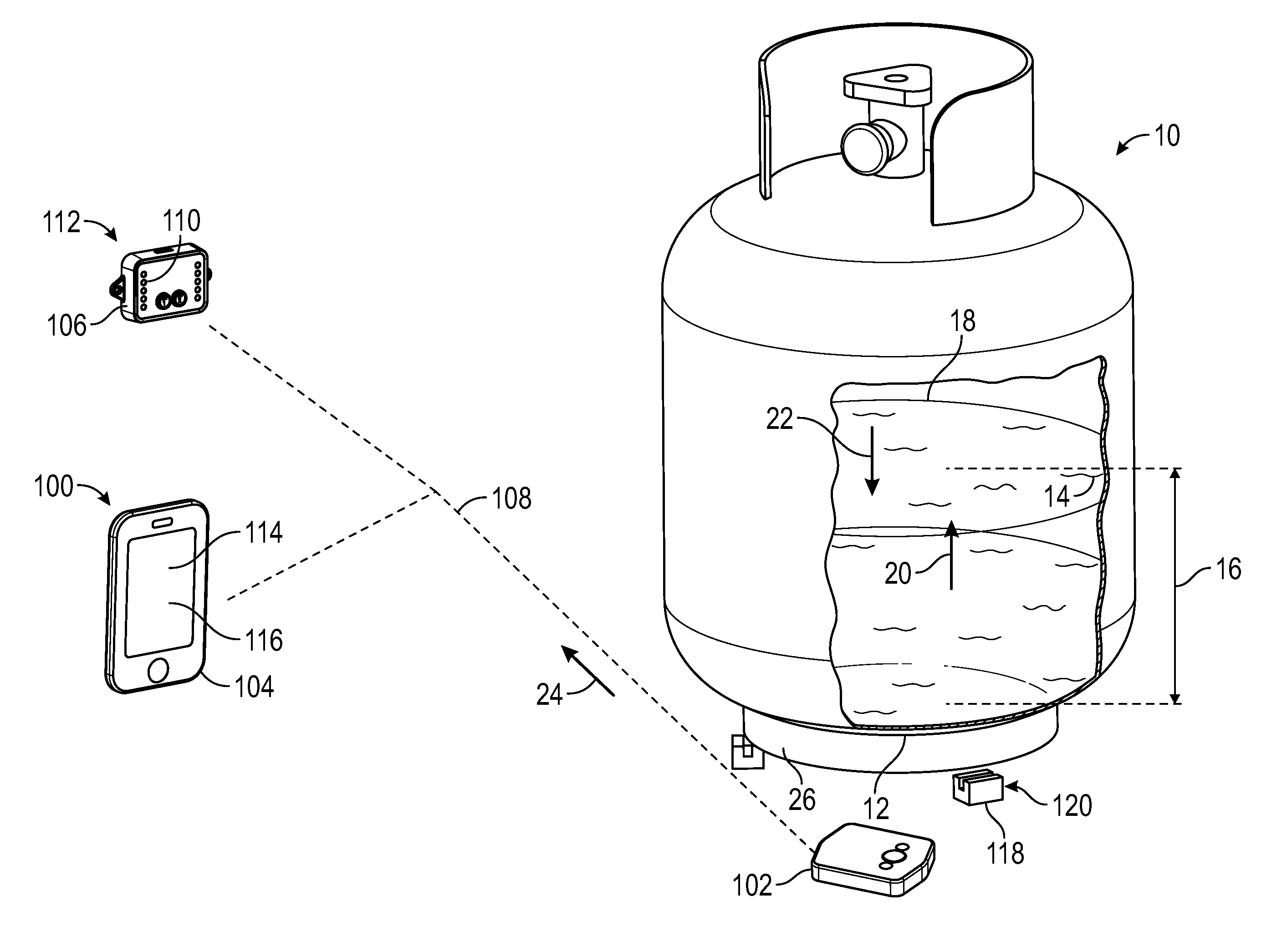
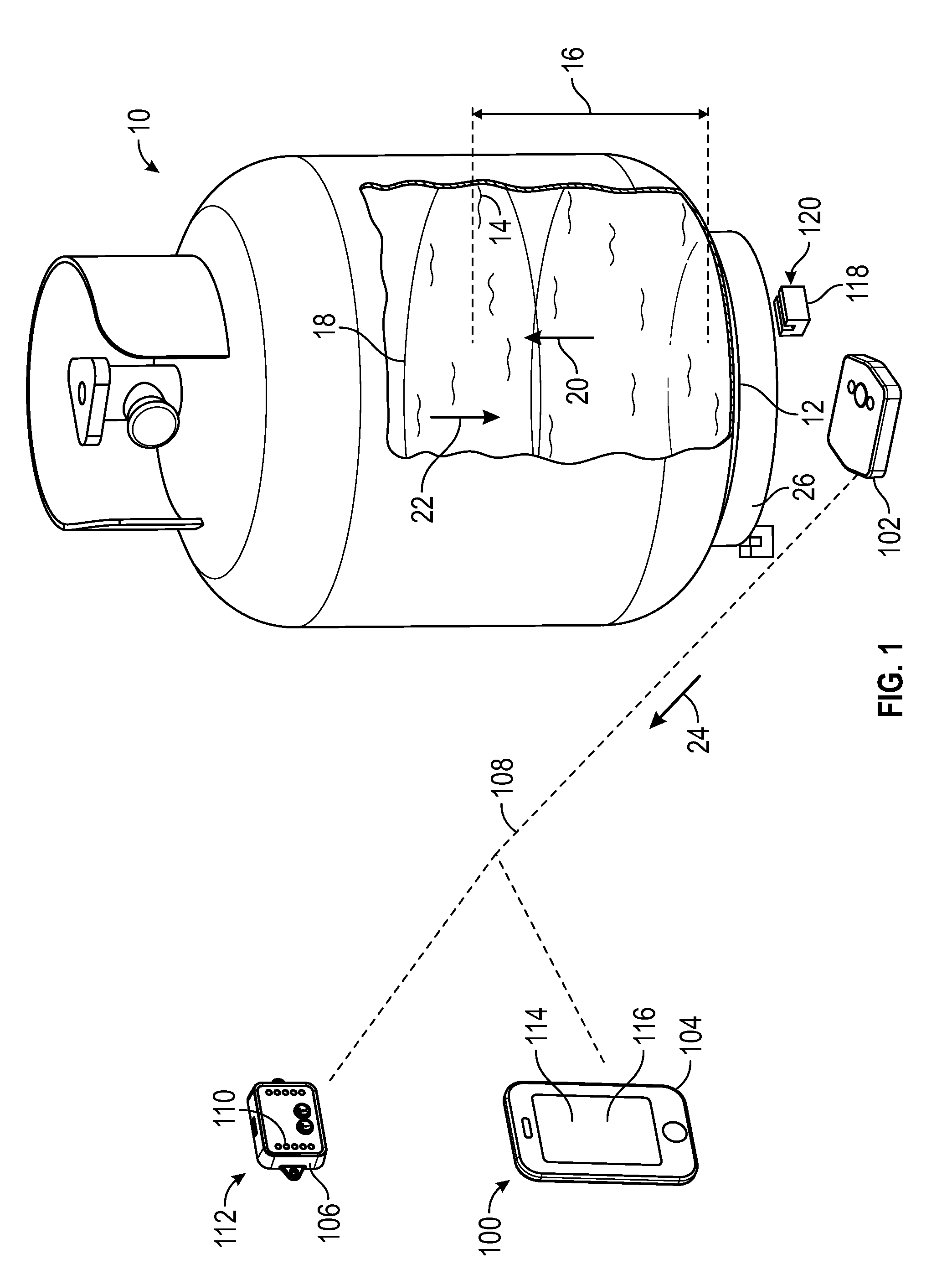
[0030]It is also contemplated that, in accordance with certain embodiments, the instructions can cause the processor to receipt a sync indicator from the sensor module. The sync indicator can be received wirelessly from the sensor module. The sync indicator can be provided wirelessly by the sensor module upon receiving a user input. The sync indicator can be p

Problems solved by technology

There have been many attempts to provide a solution to this problem, but all have various short-comings whether it is inaccuracy, reliability, or cost.
However, these techniques may not provide very good accuracy or resolution and may require that the connected appliance be in use in order to function.
The problem is that these types of pressure devices can be difficult for the normal consumer to use because pressure in the tank can vary greatly depending on the temperature of the tank, and further, pressure changes occur as gas flows from the tank during use.
So predicting an exact pressure at which one could say a tank is running low can be difficult, and it can be even more difficult to determine the exact propane level based on these pressure-sensing devices.
Thus, tare weights of tanks vary greatly, making this type of device inaccurate.
Further, some weight measuring devices that fit under the tank are not useable because there are space constraints in the appliance or RV that make it impossible to fit.
Some weight measuring devices are also built into grills

Method used


Image

  • Sensor Arrangements, Sensor Systems, and Methods for Determining Height of Liquids in Tanks
  • Sensor Arrangements, Sensor Systems, and Methods for Determining Height of Liquids in Tanks
  • Sensor Arrangements, Sensor Systems, and Methods for Determining Height of Liquids in Tanks

Examples


Embodiment Construction

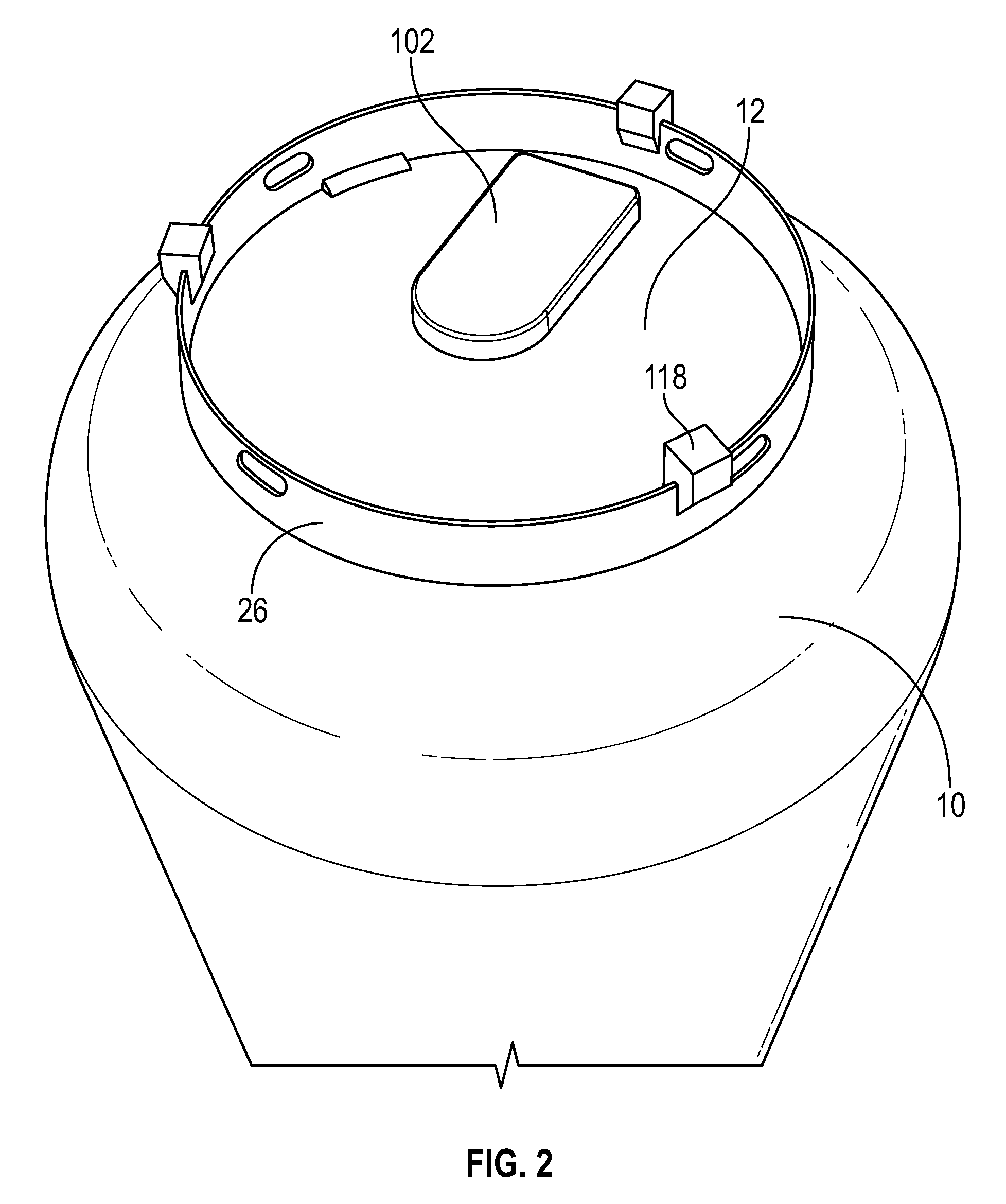
[0047]The Figures described above and the written description of specific structures and functions below are not presented to limit the scope of what Applicant has invented or the scope of the appended claims. Rather, the Figures and written description are provided to teach any person skilled in the art to make and use the invention for which patent protection is sought. Those skilled in the art will appreciate that not all features of a commercial embodiment of the invention are described or shown for the sake of clarity and understanding. Persons of skill in this art will also appreciate that the development of an actual commercial embodiment incorporating aspects of the present invention will require numerous implementation-specific decisions to achieve the developer's ultimate goal for the commercial embodiment. Such implementation-specific decisions may include, and likely are not limited to, compliance with system-related, business-related, government-related and other constr...


PUM


Abstract

A sensor arrangement for measuring liquid height in a tank can include a housing, a transducer, and a couplant. The housing can have an interior and an aperture, the aperture placing the interior of the housing in communication with the environment external to the housing. The transducer can be seated within the aperture. The couplant can be mechanically connected to the transducer and can have a compressible couplant body. The couplant body can extend between the transducer and the external environment for transmitting an acoustic pulse from the transducer to a tank bottom for measuring height of a liquid overlaying the transducer.

Description

CROSS REFERENCE TO RELATED APPLICATIONS[0001]This application claims the benefit of U.S. Provisional Application No, 62 / 211,713, filed Aug. 29, 2015, the entire contents of which are incorporated herein by reference.STATEMENT REGARDING FEDERALLY SPONSORED RESEARCH OR DEVELOPMENT[0002]Not applicable.REFERENCE TO APPENDIX[0003]Not applicable.BACKGROUND OF THE INVENTION[0004]Field of the Invention[0005]The present disclosure generally relates to determining the amount of liquid within a tank, and more particularly to sensor arrangements and systems for determining the height of liquid within tanks such as tanks containing liquefied propane gas.[0006]Description of the Related Art[0007]For as long as small portable propane tanks have been around, inventors have been trying to find low cost and reliable methods to accurately measure the propane level in the tank. There have been many attempts to provide a solution to this problem, but all have various short-comings whether it is inaccura...

Claims


Application Information

Patent Timeline
IPC IPC(8): G01F23/296G01F23/00
CPCG01F23/0069G01F23/2968G01S7/521G01F23/2962G01S15/88G08C17/00
Inventor MOORE, JOEL REESEKAUFMAN, JONATHAN LOUISPECK, JASON DUANE
Owner MOPEKA PROD LLC
Why Eureka
Try Eureka