
Frequency reconfigurable liquid medium resonant antenna

A technology of liquid medium and resonant antenna, which is applied in the direction of antenna, antenna grounding device, antenna grounding switch structure connection, etc., can solve the problems of high quality factor of pure water antenna, low antenna radiation efficiency, narrow antenna bandwidth, etc., and achieve compact antenna Type design, reduce the quality factor, improve the effect of bandwidth

Active Publication Date: 2019-02-26
NANJING UNIV OF AERONAUTICS & ASTRONAUTICS
View PDF6 Cites 9 Cited by
  • Summary
  • Abstract
  • Description
  • Claims
  • Application Information

AI Technical Summary

Problems solved by technology

[0004] The design of pure water dielectric resonant antennas currently faces two problems: 1) The pure water antenna has a high quality factor (Quality Factor, Q) and the bandwidth of the antenna is narrow, which limits the application of some broadband; 2) The flow of pure water Various advantages such as stability and transparency have not been fully utilized. Water is a liquid material suitable for reconfigurable liquid antennas. On the basis of not relying on external active devices, it can form some structures that are relatively complex and difficult to form solid materials. The antenna structure overcomes the limitations of existing reconfigurable antennas. Reconfigurable antennas loaded with active devices will reduce the antenna radiation efficiency, and the bias circuit introduced by active devices will also complicate the antenna structure. Currently, liquid reconfigurable The antenna design is still relatively limited, and the unique advantages of liquid have not been fully utilized, so there is a large research space
[0005] In summary, the existing liquid dielectric resonant antennas still have certain limitations in terms of broadband and reconfigurability

Method used


Image

  • Frequency reconfigurable liquid medium resonant antenna
  • Frequency reconfigurable liquid medium resonant antenna
  • Frequency reconfigurable liquid medium resonant antenna

Examples


Embodiment Construction

[0024] The present invention will be further explained below in conjunction with the accompanying drawings.

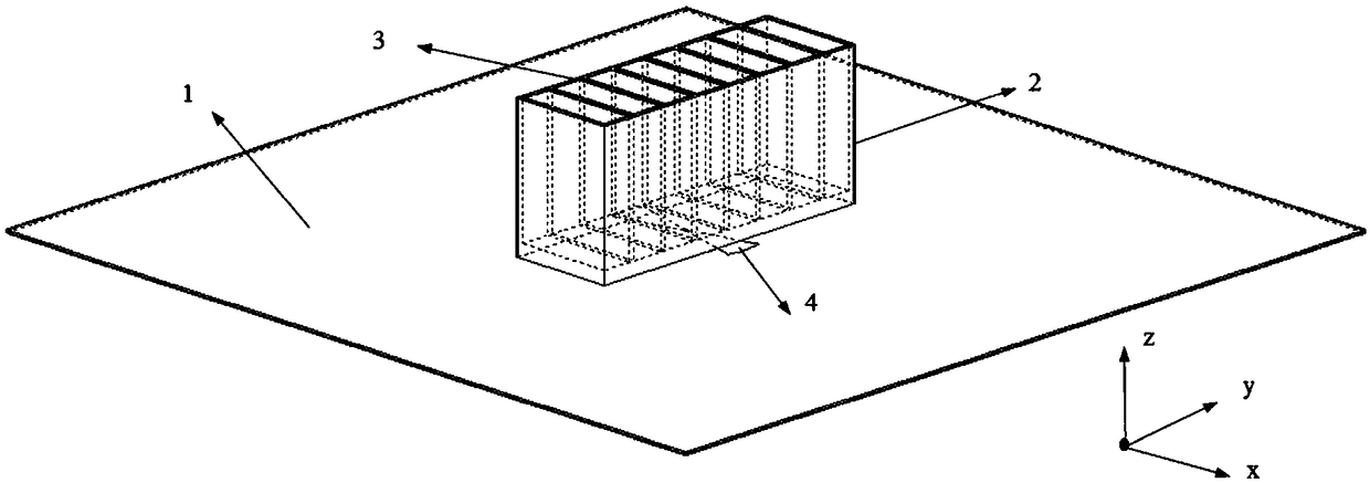
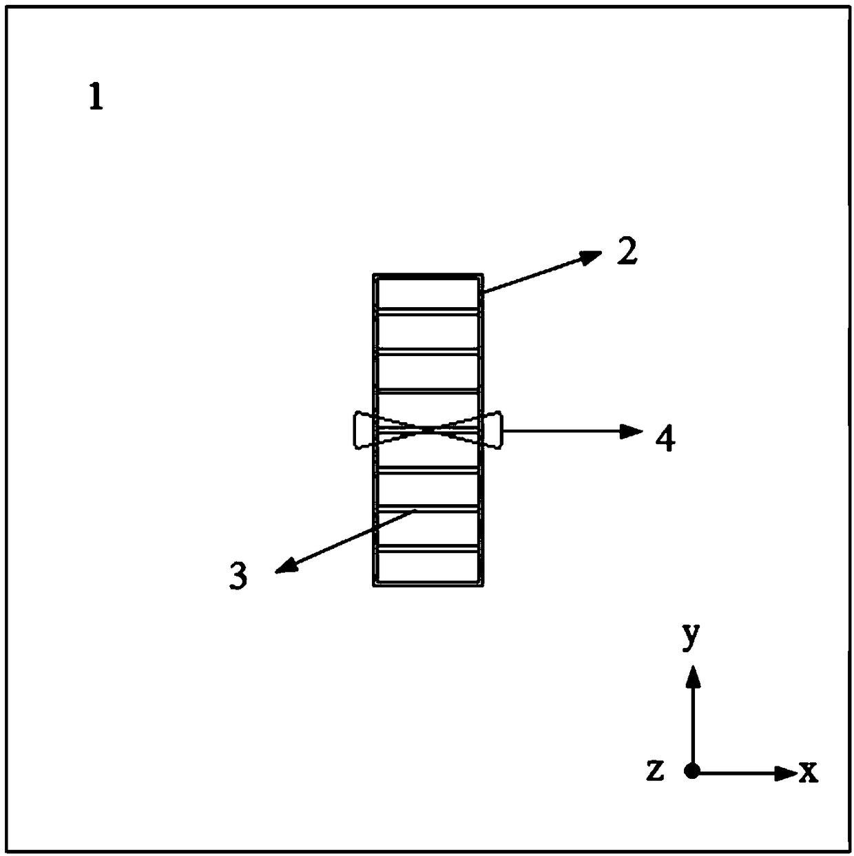
[0025] Such as Figure 1-4 As shown, a frequency reconfigurable liquid dielectric resonant antenna includes: a ground plate 1 , a liquid dielectric resonator 2 fixed on the ground plate 1 , and a bow-tie feed port 4 arranged on the surface of the ground plate 1 . The liquid dielectric resonator 2 includes a transparent cuboid liquid container formed by a transparent plate with a dielectric constant of 3-6 and a liquid medium. The bottom thickness of the transparent cuboid liquid container is set by the equivalent dielectric constant method. The transparent cuboid liquid container is evenly divided into multiple compartments by several transparent partitions 3 vertical to the grounding plate 1, and the liquid medium is pure water. The resonant antenna adjusts the TE by the number of consecutive compartments injected with pure water and / or the height of the pure water i...


PUM

PropertyMeasurementUnit
Widthaaaaaaaaaa
Side wall thicknessaaaaaaaaaa
Bottom thicknessaaaaaaaaaa

Abstract

The invention discloses a frequency reconfigurable liquid medium resonant antenna which comprises a liquid dielectric resonator and a ground plate. The main radiating element of the antenna is the liquid dielectric resonator composed of a transparent cuboid liquid container and pure water. The liquid container is evenly divided into a number of intervals. The size of the liquid medium resonator can be changed by adding pure water at a specific interval. The resonant frequency of the liquid resonator can be reconstructed. In addition, the liquid height in each interval is also adjustable. The operating frequency of the liquid resonant antenna can be further adjusted under different liquid interval combinations. According to the invention, liquid medium resonance structures of various sizescan be formed in the same structure without using an active device and a matching circuit; compact antenna scale, high radiation efficiency and wide frequency band coverage are realized; and the design can be widely used in various applications in the field of wireless communications.

Description

technical field [0001] The invention belongs to the technical field of antennas, in particular to a liquid medium resonant antenna. Background technique [0002] With the development of wireless communication systems in the direction of large-capacity, multi-function, and ultra-wideband, the system also puts forward higher requirements for antennas, not only requiring small antenna size and wide frequency bandwidth, but also requiring high antenna gain, low cost, and high radar cross-section Small. Traditional metal antennas are difficult to meet the requirements of the system. Therefore, the research on new antennas with application prospects is particularly urgent. Among the new antennas, liquid antennas have attracted extensive attention from scholars at home and abroad in recent years due to their advantages such as flexible structure, strong reconfigurability, low cost, and wide application range. [0003] Pure water (also known as distilled water) is a liquid medium ...

Claims


Application Information

Patent Timeline
IPC IPC(8): H01Q1/36H01Q1/48H01Q1/50H01Q5/10H01Q5/307H01Q5/50
CPCH01Q1/36H01Q1/48H01Q1/50H01Q5/10H01Q5/307H01Q5/50
Inventor 邢蕾朱佳佳徐千
Owner NANJING UNIV OF AERONAUTICS & ASTRONAUTICS
Learn More