An antenna with reconfigurable frequency and pattern based on flexible materials

A technology of flexible materials and directional diagrams, applied in flexible antennas, antennas, folded antennas, etc., can solve the problems of unoptimized antenna utilization, difficulty in reconfigurable antennas, inefficient use of radio base stations, etc., to achieve Not easy to fall off, good adhesion, wide application effect

Active Publication Date: 2020-07-17
HEFEI UNIV OF TECH
View PDF13 Cites 0 Cited by
  • Summary
  • Abstract
  • Description
  • Claims
  • Application Information

AI Technical Summary

Problems solved by technology

To cope with peak traffic, operators will simply add more base stations to over-build the network, resulting in inefficient use of radio base stations, so new methods are needed to improve the resource utilization of base stations
In the current reconfigurable antenna, the utilization rate of the antenna is not optimal, and the reconfigurable antenna pattern or polarization cannot be realized when the antenna frequency is reconfigurable; at the same time, for the antenna Reconfigurable implementation is more difficult. Most of them use diodes as switches to control radiation elements, or metamaterials, and use MEMS to achieve control. The realization of these antennas is more troublesome.

Method used


Image

  • An antenna with reconfigurable frequency and pattern based on flexible materials
  • An antenna with reconfigurable frequency and pattern based on flexible materials
  • An antenna with reconfigurable frequency and pattern based on flexible materials

Examples


Embodiment 1

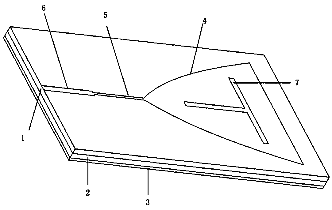
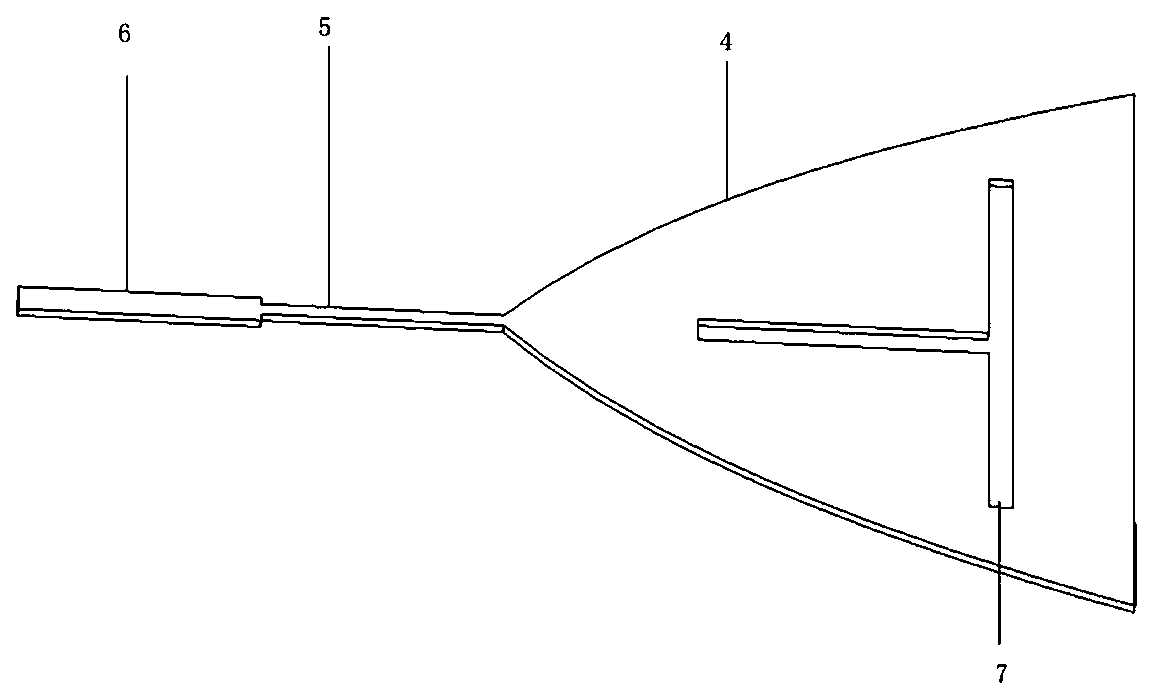
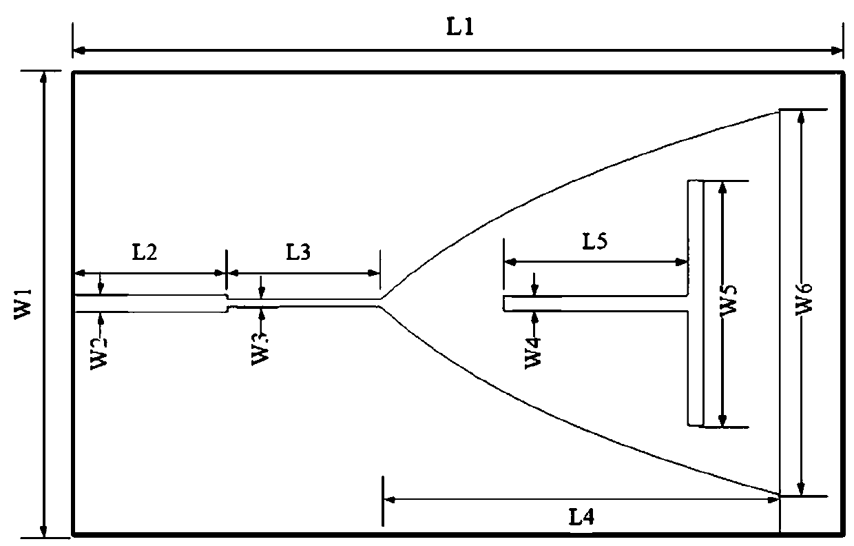
[0031] see figure 1 , a reconfigurable antenna based on frequency and pattern of flexible materials includes a flexible dielectric plate and a microstrip patch; the flexible dielectric plate includes a radiation conductive layer 1, a flexible dielectric layer 2 and a ground layer 3 arranged in sequence; The conductive layer 1 is an inverted isosceles triangle, the flexible dielectric layer 2 and the ground layer 3 are rectangular plates; the width W1 of the rectangular plate is 30 mm, and the length L1 is 50 mm; the microstrip patch is arranged on the radiating conductive layer 1 . The material of the radiating conductive layer 1 and the material of the grounding layer 3 are both graphene, and the thickness of the radiating conductive layer 1 and the thickness of the grounding layer 3 are both 35um. The flexible dielectric layer 2 is composed of an upper flexible dielectric layer and a lower flexible dielectric layer, both made of polyimide, each layer having a thickness of 0....


PUM


Abstract

The invention relates to a frequency and pattern reconfigurable antenna based on a flexible material. The antenna comprises a flexible dielectric plate and a microstrip patch; the flexible dielectricplate is composed of a radiation conductive layer, a flexible dielectric layer and a ground layer which are connected in sequence in an overlapping manner. the microstrip patch is arranged on the radiation conductive layer; the microstrip patch consists of a radiating arm, first-order microstrip line and second-order microstrip line; the radiating arm is in the shape of an inverted isosceles triangle; the radiating arm and the radiating conductive layer are provided with T-shaped groove lines corresponding to each other, and the transverse groove lines of the T-shaped groove lines are parallelto the bottom sides of the isosceles triangle. As a microstrip patch antenna, the operating frequency is 6.8 GHz when it is not bent. When the bending angle is less than 5 degrees, the frequency of the antenna is reconfigurable, and the transformation from single-band antenna to dual-band antenna is realized. The frequency of the antenna is reconfigurable under the dual-band effect. When the bending angle is 40 to 90 degrees, the antenna pattern can be reconfigurable to deflect the antenna direction, and the antenna is transformed from a microstrip patch antenna into a monopole antenna.

Description

technical field [0001] The invention belongs to the technical field of flexible microwave circuits and systems, and in particular relates to reconfigurable microwave and millimeter wave antennas. Background technique [0002] Antennas play an important role in wireless communication systems. With the continuous development of modern communication systems, wireless communication systems have higher and higher requirements for antennas, such as large capacity, ultra-wideband, and multi-functional integration. Various methods of mounting multiple antennas or forming arrays on the same platform seriously increase the cost and weight of the wireless communication system. In order to meet the development needs of the wireless communication system, reconfigurable antennas have been proposed. [0003] As a new type of antenna, the reconfigurable antenna was proposed in the 1960s. In order to reduce the weight of the antenna loaded on the radar, reduce the cost and reduce the radar s...

Claims


Application Information

Patent Timeline
Patent Type & Authority Patents(China)
IPC IPC(8): H01Q1/38H01Q1/36H01Q1/50H01Q1/08H01Q3/01H01Q5/20H01Q5/307H01Q9/04H01Q9/40
CPCH01Q1/085H01Q1/368H01Q1/38H01Q1/50H01Q3/01H01Q5/20H01Q5/307H01Q9/045H01Q9/40
Inventor 桑磊戴柯寒郭肖肖黄文
Owner HEFEI UNIV OF TECH
Why Eureka
Try Eureka