Zero net energy DC datacenter power distribution architecture

a datacenter and power distribution system technology, applied in the direction of ac-dc network circuit arrangement, dc source parallel operation, apparatus without intermediate ac conversion, etc., can solve the problems of power distribution system suffering, energy cost, and failure to effectively power a datacenter

Active Publication Date: 2017-03-02
ABB (SCHWEIZ) AG
View PDF4 Cites 13 Cited by
  • Summary
  • Abstract
  • Description
  • Claims
  • Application Information

AI Technical Summary

Problems solved by technology

Present efforts in ZNE power distribution systems suffer from a number of shortcomings and disadvantages.
Existing proposals fail to effectively power a datacenter by regulating the power generated by multiple power sources in order to reduce power consumption from a utility grid and reduce the energy cost of the power distribution system.

Method used


Image

  • Zero net energy DC datacenter power distribution architecture
  • Zero net energy DC datacenter power distribution architecture
  • Zero net energy DC datacenter power distribution architecture

Examples


Embodiment Construction

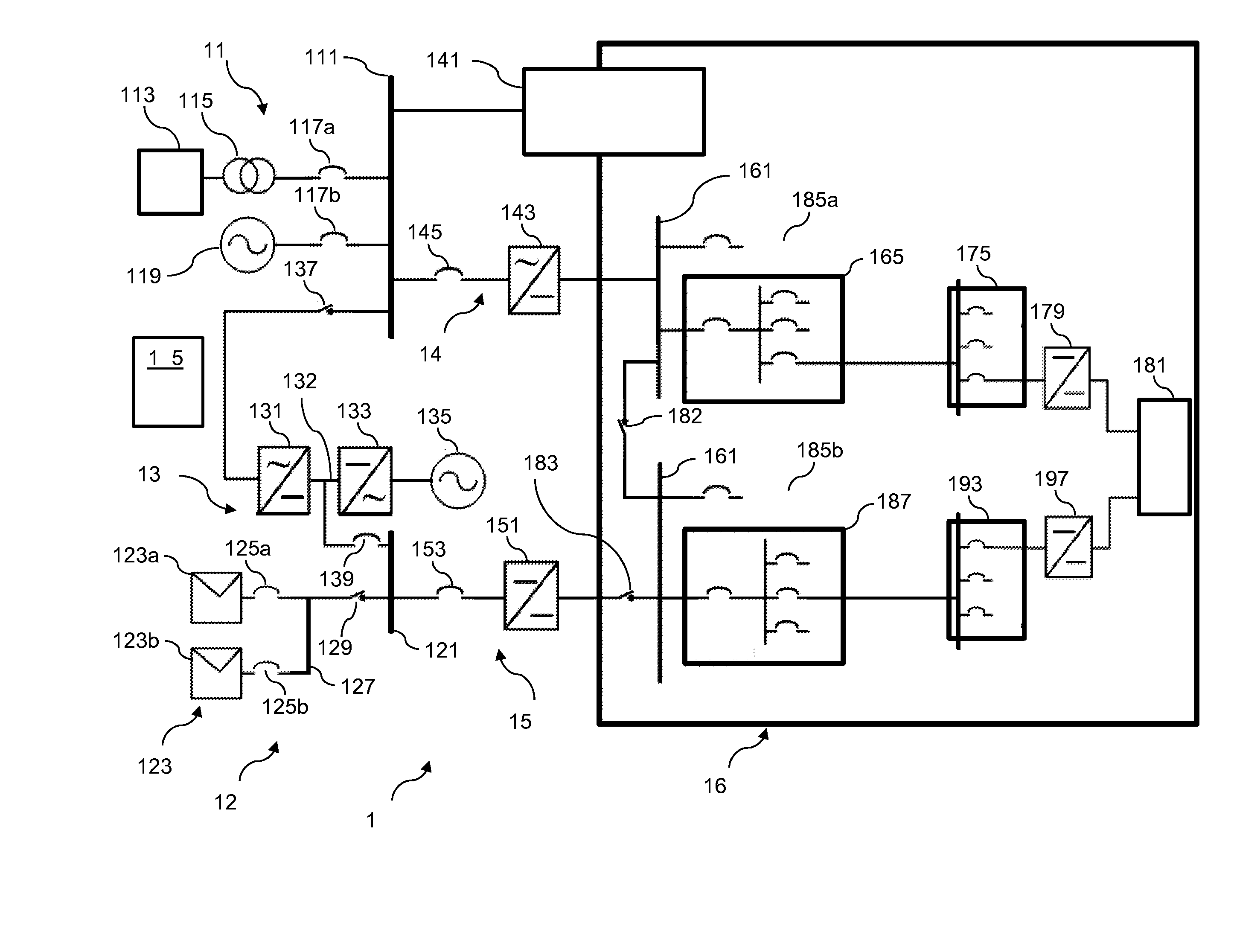
[0007]With reference to FIG. 1 there is illustrated an exemplary datacenter power supply system 100. System 100 includes AC power system 110 coupled to an AC power bus 111. AC power system 110 includes power grid 113, transformer 115, and circuit breaker 117a. Power grid 113 is operatively coupled to AC power bus 111 by way of power transformer 115 and circuit breaker 117a. Grid 113 is structured to selectably transfer power to bus 111 and to selectably receive power from bus 111. In certain embodiments, grid 113 is a utility grid. In the illustrated embodiment, transformer 115 is a step down transformer. In certain embodiments, transformer 115 is a step up transformer. In still another embodiment, transformer 115 is not present.

[0008]Breaker 117a is structured to disrupt the flow of current between grid 113 and AC power bus 111. Breaker 117a may be a mechanical circuit breaker, solid state circuit breaker, switch, semiconductor device, contactor, or any other device structured to d...


PUM


Abstract

Unique systems, methods, techniques, and apparatuses of datacenter power supply systems are disclosed. One exemplary embodiment is a datacenter power supply system comprising an AC power bus structured to selectably receive AC power from an AC power grid and a AC generator and structured to provide AC power to one or more AC datacenter loads and an AC / DC converter, a DC power generation system structured to provide DC power to a DC / DC converter, a DC power bus structured to selectably receive power from the AC / DC converter and the DC / DC converter and to provide DC power to a plurality of DC datacenter loads, and an electronic control system structured to selectably control the datacenter power supply system to operate in plurality of modes.

Description

BACKGROUND[0001]The present application relates generally to a power distribution system and more particularly, but not exclusively to a zero net energy (ZNE) DC datacenter power distribution system. Recent developments in renewable energy technology and DC grid technology have facilitated development of ZNE power distribution systems. Present efforts in ZNE power distribution systems suffer from a number of shortcomings and disadvantages. Existing proposals fail to effectively power a datacenter by regulating the power generated by multiple power sources in order to reduce power consumption from a utility grid and reduce the energy cost of the power distribution system. There remain unmet needs respecting power supply regulation, reliability, and power quality. Further unmet needs include reducing energy costs and preventing loss of power to a datacenter. There is a significant need for the unique apparatuses, methods, systems and techniques disclosed herein.DISCLOSURE[0002]For the...

Claims


Application Information

Patent Timeline
Patent Type & Authority Applications(United States)
IPC IPC(8): H02J3/38H02M3/04H02M7/04H02J5/00
CPCH02J3/381H02J5/00H02M7/04H02M3/04H02J3/383H02J1/10H02J3/38H02J4/00
Inventor WANG, ZHENYUANAHMED, SARALIU, JUHUA
Owner ABB (SCHWEIZ) AG
Why Eureka
Try Eureka