Communications device, infrastructure equipment and methods for LTE communication within unused GSM channels

a technology of infrastructure equipment and communication devices, applied in the direction of payload allocation, transmission path sub-channel allocation, electrical equipment, etc., can solve the problems of network capacity and geographical areas that can be served by such networks, efficient use of available communications resources, etc., to improve latency and maximum data rate, increase the data rate of the communication devi

Active Publication Date: 2017-03-02
CONVIDA WIRELESS LLC
View PDF8 Cites 7 Cited by
  • Summary
  • Abstract
  • Description
  • Claims
  • Application Information

AI Technical Summary

Benefits of technology

[0013]The combining of resources across a plurality of minimum frequency units over a single time unit provides an increased data rate for a communications device compared to transmissions combining over a plurality of time units. This will therefore provide a communications system which has an improved latency and maximum data rate for individual communications devices.
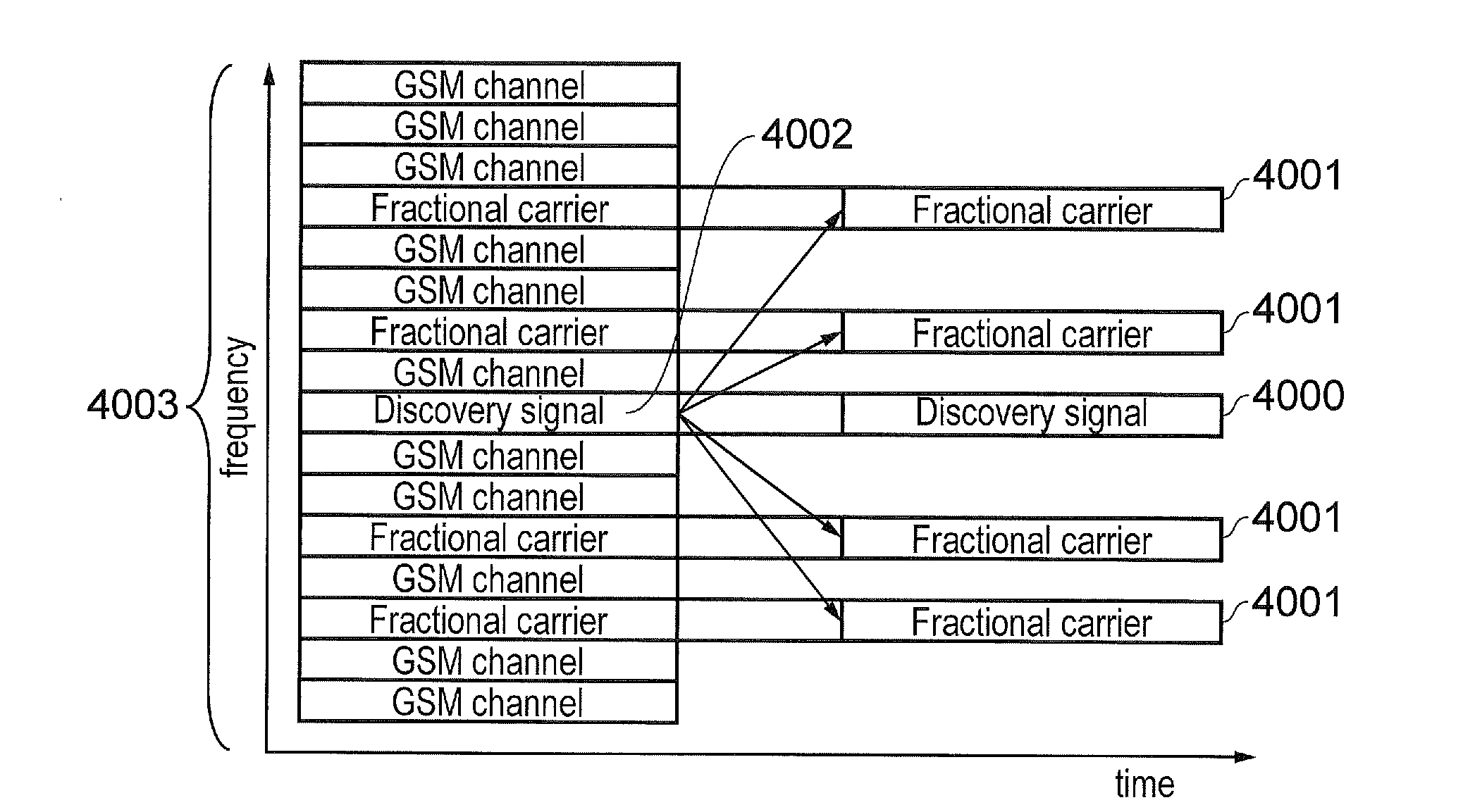
[0014]Embodiments of the present technique can provide an arrangement for a communications device to discover the one or more frequency resources, which therefore allows a stand-alone deployment of fractional LTE carriers in non-contiguous frequency resources without having to resort to cross-carrier scheduling in carrier aggregation.

Problems solved by technology

However, although the coverage and capacity of fourth generation networks is expected to significantly exceed those of previous generations of communications networks, there are still limitations on network capacity and the geographical areas that can be served by such networks.
Making efficient use of available communications resources represents a technical problem, for example where spectrum becomes available within a frequency band.

Method used


Image

  • Communications device, infrastructure equipment and methods for LTE communication within unused GSM channels
  • Communications device, infrastructure equipment and methods for LTE communication within unused GSM channels
  • Communications device, infrastructure equipment and methods for LTE communication within unused GSM channels

Examples


example implementation

[0148]FIG. 26 provides a schematic diagram of a UE 2700 and an eNodeB 2710 in which examples of the presently disclosed technique may be implemented. The UE includes a transmitter 2701, a receiver 2702 and a controller 2703, where the controller is configured to control the receiver 2702 to detect signals representing control data and user data transmitted by the eNodeB 2710, and to estimate the data conveyed by the signals. The controller 2703 is also configured to control the transmitter 2701 to transmit signals representing uplink control data and user data to the eNodeB. Although in FIG. 26 the UE 2700 is illustrated as comprising a separate transmitter and receiver, it may instead comprise a transceiver which is configured in combination with the controller to implement the aforementioned features and techniques. The controller 2703 may comprise a processor unit which is suitably configured / programmed to provide the desired functionality described herein using conventional prog...


PUM


Abstract

A communications device includes a receiver, a transmitter, a controller. The receiver is configured to receive signals representing downlink data from an infrastructure equipment of a wireless communications network via a wireless access interface having a logical baseband frame structure. The transmitter is configured to transmit signals representing uplink data to the infrastructure equipment via the wireless access interface, the logical baseband frame structure being formed from one or more minimum frequency units and one or more time units to form communications resources for allocation by the infrastructure equipment to the communications device. The controller is configured to receive a signal providing an indication of one or more frequency resources available within a host frequency band, to combine the one or more frequency resources within the host frequency band in time and/or frequency to form the one or more of the minimum frequency units of the logical baseband frame structure.

Description

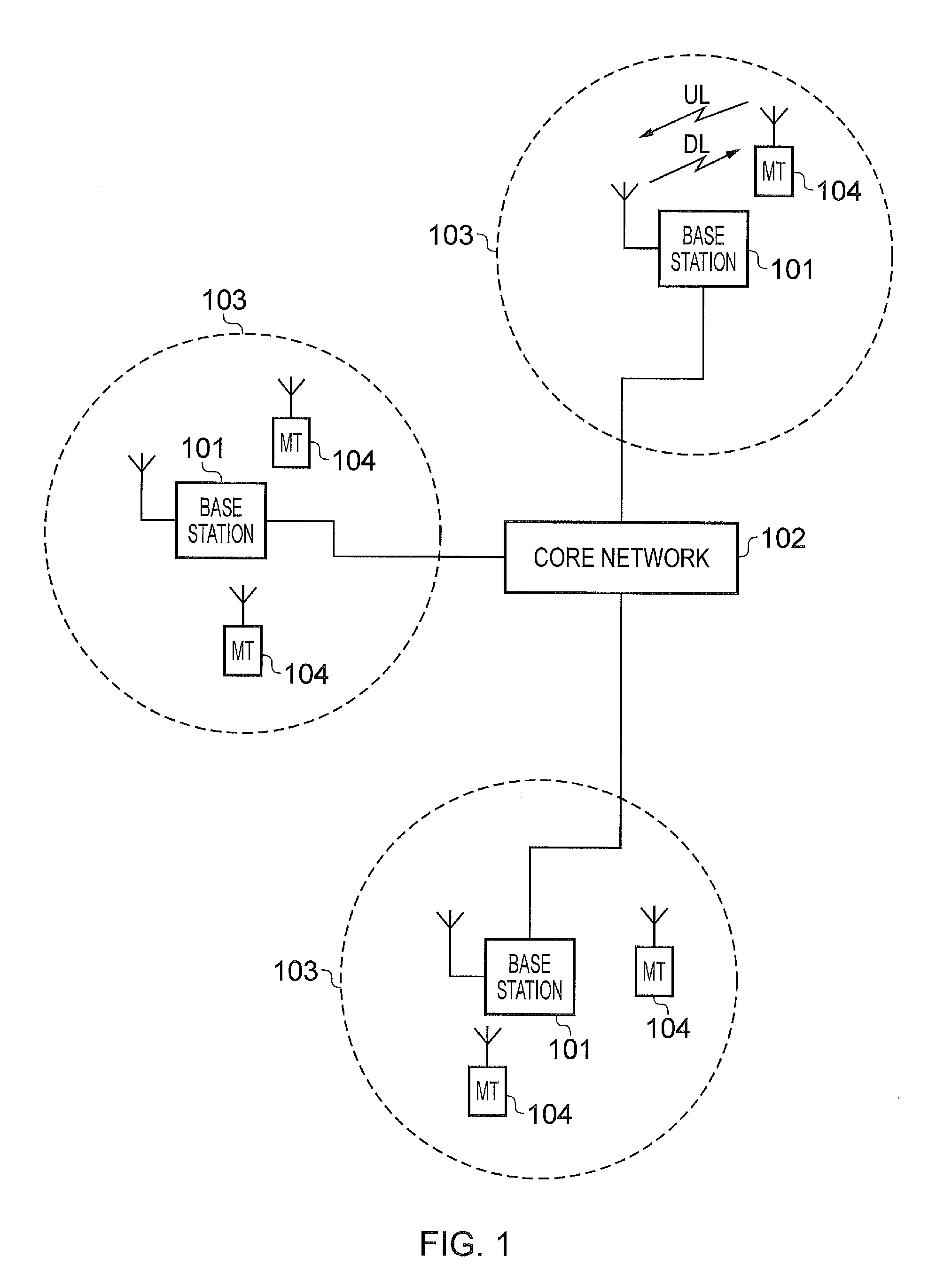
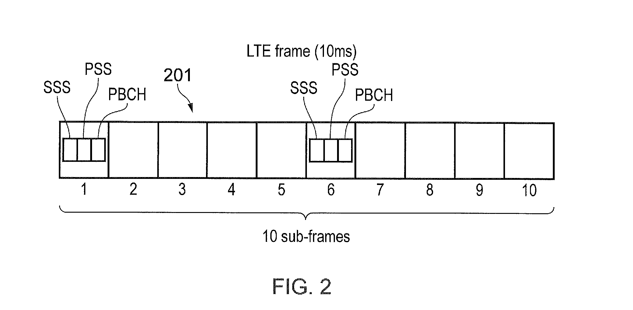
FIELD OF THE DISCLOSURE[0001]The present disclosure relates to communications devices and methods of communicating data, infrastructure equipment for mobile communications networks and methods of communicating with communications devices using mobile communications networks.[0002]The present application claims the priority of EP14158990.3 the contents of which are herein incorporated by reference.BACKGROUND OF THE DISCLOSURE[0003]Mobile telecommunication systems, such as those based on the 3GPP defined UMTS and Long Term Evolution (LTE) architecture, are able to support more sophisticated services than simple voice and messaging services offered by previous generations of mobile telecommunication systems. For example, with the improved radio interface and enhanced data rates provided by LTE systems, a user is able to enjoy high data rate applications such as video streaming and video conferencing on mobile communications devices that would previously only have been available via a f...

Claims


Application Information

Patent Timeline
Patent Type & Authority Applications(United States)
IPC IPC(8): H04W72/04H04W8/22H04W16/14
CPCH04W72/048H04W16/14H04W72/0406H04W72/0453H04W8/22H04W72/0446H04L5/0044H04L27/0006H04W72/51H04W72/20
Inventor KAHTAVA, JUSSI TAPANIWEBB, MATTHEW WILLIAM
Owner CONVIDA WIRELESS LLC
Why Eureka
Try Eureka