
Lighting control system

a control system and light technology, applied in the field of light control systems, can solve the problems of severe pms symptoms and inability to sufficiently relieve, and achieve the effect of reducing the symptoms of pms

Inactive Publication Date: 2017-03-09
PANASONIC INTELLECTUAL PROPERTY MANAGEMENT CO LTD
View PDF3 Cites 4 Cited by
  • Summary
  • Abstract
  • Description
  • Claims
  • Application Information

AI Technical Summary

Benefits of technology

The present disclosure provides a lighting control system that can help alleviate the symptoms of PMS based on its severity. This means that the system can adjust its lighting to make the person's mood better, helping them to feel better and more productive during PMS.

Problems solved by technology

The technique disclosed by Japanese Unexamined Patent Application Publication No. 2003-164527, however, is to control only the temperature environment in a bed, and not targeting a lighting environment.
For example, the symptoms of PMS become severe when a user does a great amount of activity, or become mild when a user is exposed to sunlight or illuminating light for a long period of time.
For instance, there are cases where it is not possible to sufficiently alleviate the symptoms of PMS even when the symptoms of PMS are severe.

Method used


Image

  • Lighting control system
  • Lighting control system
  • Lighting control system

Examples


embodiment 1

[0030]The following describes Embodiment 1 with reference to FIG. 3 to FIG. 5.

[0031][Configuration of Lighting Control System]

[0032]FIG. 3 is a diagram illustrating a configuration of lighting control system 1 according to Embodiment 1.

[0033]Lighting control system 1 controls a lighting device according to biological information related to a biological body of a user and environmental information related to a surrounding environment of the user, and includes biological information obtainer 10, environmental information obtainer 20, severity determiner 40, and lighting controller 50.

[0034]Biological information obtainer 10 obtains biological information related to a biological body of the user. Biological information includes at least one of information items indicating a basal body temperature, an amount of luteinizing hormone secretion, an amount of luteohormone secretion, an amount of estrogenic hormone secretion, an amount of activity, blinking, electrodermal activity, brain wave...

embodiment 2

[0082]The following describes Embodiment 2 with reference to FIG. 6 and FIG. 7.

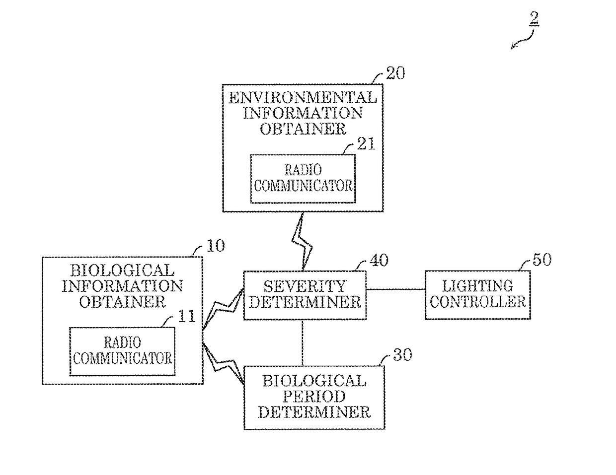
[0083]Lighting control system 2 according to the present embodiment is different from lighting control system 1 according to Embodiment 1 in that lighting control system 2 includes biological period determiner 30, and is the same as lighting control system 1 according to Embodiment 1 other than the inclusion of biological period determiner 30. Accordingly, detailed description will be omitted, and the following describes mainly biological period determiner 30.

[0084]FIG. 6 is a diagram illustrating a configuration of lighting control system 2 according to Embodiment 2. As illustrated in FIG. 6, lighting control system 2 has the configuration of lighting control system 1 to which biological period determiner 30 is added. Biological period determiner 30 is included, for example, in lighting device 200 illustrated in FIG. 5, and wirelessly communicates with radio communicator 11.

[0085]FIG. 7 is a flowchart il...


PUM


Abstract

A lighting control system includes: a biological information obtainer which obtains biological information related to a biological body of a user; an environmental information obtainer which obtains environmental information related to a surrounding environment of the user; a severity determiner which determines a severity of premenstrual syndrome (PMS) based on the biological information obtained by the biological information obtainer and the environmental information obtained by the environmental information obtainer; and a lighting controller which controls a lighting device based on the severity determined by the severity determiner.

Description

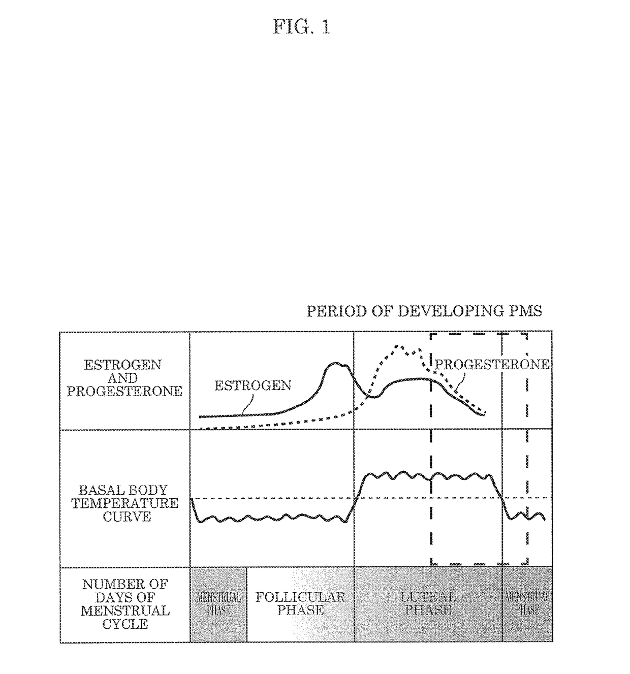
CROSS REFERENCE TO RELATED APPLICATION[0001]This application claims the benefit of priority of Japanese Patent Application Number 2015-176996 filed on Sep. 8, 2015, the entire content of which is hereby incorporated by reference.BACKGROUND[0002]1. Technical Field[0003]The present disclosure relates to a lighting control system corresponding to biological information and environmental information.[0004]2. Description of the Related Art[0005]A device which estimates a change in a physical condition of a user which appears in a menstrual cycle of the user, based on biological information such as a basal body temperature, and controls a temperature environment in a bed according to the estimated physical condition of the user is known. For example, Japanese Unexamined Patent Application Publication No. 2003-164527 discloses a technique related to such a device.SUMMARY[0006]In the menstrual cycle, there is a period of developing premenstrual syndrome (PMS). It is known that the symptoms ...

Claims


Application Information

Patent Timeline
Patent Type & Authority Applications(United States)
IPC IPC(8): A61N5/06A61B10/00H05B37/02
CPCA61N5/0618H05B37/0227H05B37/0272A61B2010/0029A61N2005/0626A61B2010/0019A61B10/0012H05B47/10H05B47/11H05B47/105H05B47/19Y02B20/40H05B47/165H05B47/1985
Inventor FUJIWARA, YURITSUKITANI, AYAKOTODA, NAOHIRO
Owner PANASONIC INTELLECTUAL PROPERTY MANAGEMENT CO LTD
Learn More