Handheld electric tool

a technology of electric tools and electric motors, applied in the direction of motor driven pruning saws, cutters, agricultural tools and machines, etc., can solve the problems of powering devices, oftentimes unreasonable, malfunction and damage, etc., and achieve excellent cooling effects, high cooling efficiency, and facilitate the disassembly effect of users

Active Publication Date: 2017-03-09
CHERVON HK LTD WANCHAI
View PDF7 Cites 18 Cited by
  • Summary
  • Abstract
  • Description
  • Claims
  • Application Information

AI Technical Summary

Benefits of technology

[0019]Furthermore, the handheld electric tool may include: a manipulating handle for facilitating a user to manipulate the handheld electric tool. The manipulating handle is disposed between the powering device and the working device.
[0051]Furthermore, the tank cover may include: a cover body for facilitating a user to disassemble the tank cover, and a sealing gasket configured to seal the tank cover. The cover body may include: a cover body top portion configured to cover the oil inlet, and a cover body side portion configured to fix the tank cover to the tank body. The cover body top portion and the cover body side portion cooperatively form a cover body chamber. The sealing gasket is disposed in the cover body chamber. The cover body top portion is formed with a disassembly groove for facilitating a user to disassemble. The disassembly groove is formed at an opposite direction with respect to the cover body chamber.
[0052]Accordingly, the disclosure can achieve the advantages that the handheld electric tool has excellent cooling effect and therefore the cooling efficiency is high.

Problems solved by technology

However, the arrangement of the electric motor, the circuit board and the transmission device of the traditional powering device is oftentimes unreasonable and / or unsatisfactory for its intended purpose as heat generated by the electric motor and the circuit board during a working process cannot be dissipated in time and thereby can lead to malfunction and damage.
The traditional manipulating member for speed control is disposed just above a handle, which may make it difficult for a user to control the speed while also controlling the trigger.
However, for the traditional plugged structure, the transmission shafts in the long-rod structures each have a large degree of freedom, thus producing a wobble such that the two transmission shafts are not easily combined into an integral structure.
After the power tool is used for a period of time, the oil in the oil tank is consumed and the tank may be depleted.
Therefore, the user often needs to open a tank cover to refuel the oil tank, which can easily result in the problem of losing the often disassembled tank cover.
Furthermore, the supporting frame is formed with an installing hole.

Method used


Image

  • Handheld electric tool
  • Handheld electric tool
  • Handheld electric tool

Examples


Embodiment Construction

[0072]In the following, with reference to accompanying drawings and concrete embodiments, the disclosure will be described in detail.

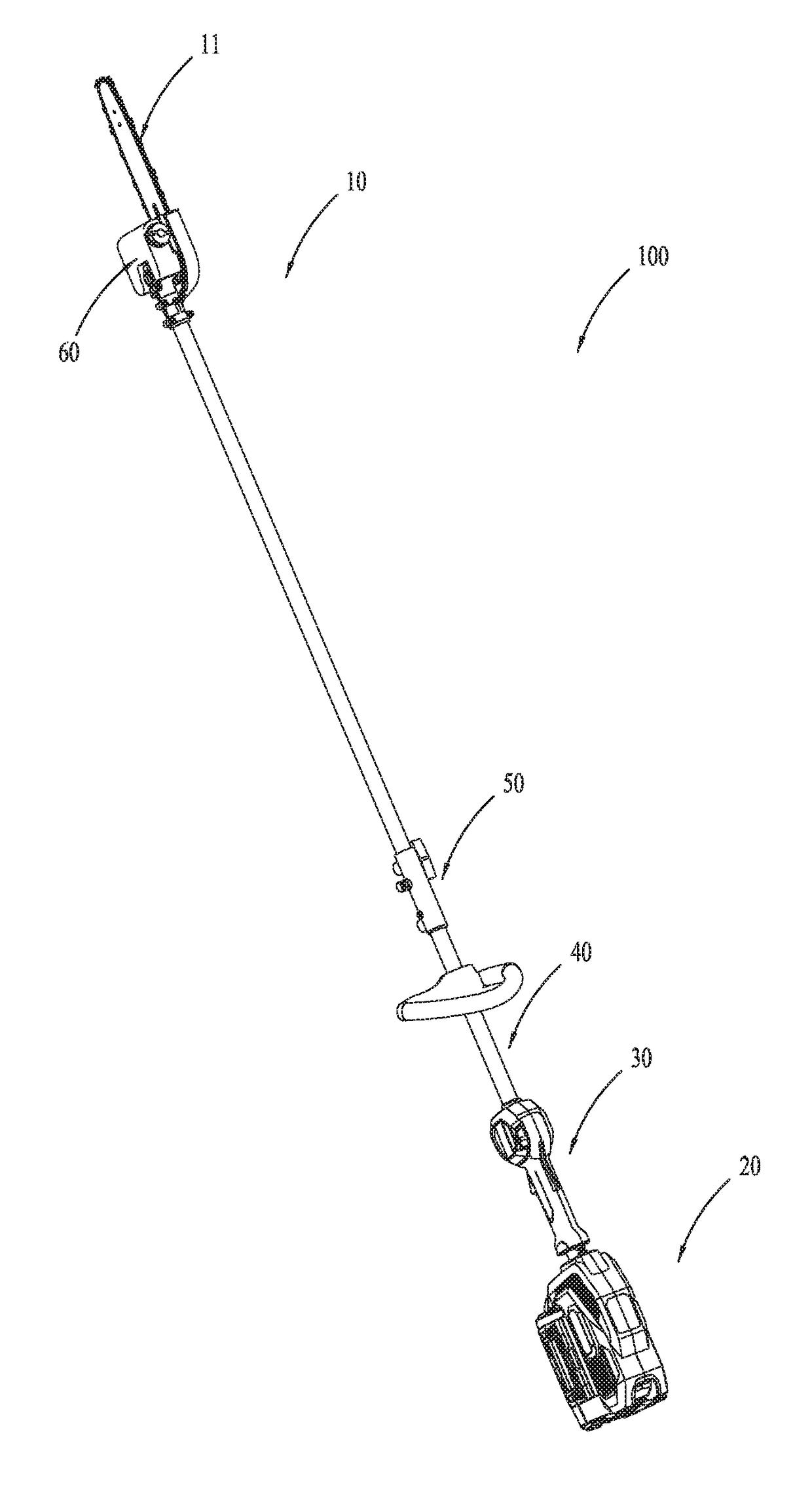
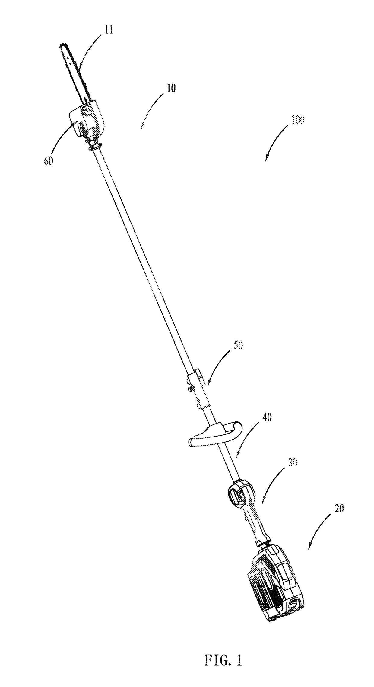
[0073]An example handheld power tool 100 as illustrated in FIG. 1 includes a working device 10, a powering device 20, a manipulating device 30, a connecting device 40, and a sleeve device 50.

[0074]The working device 10 is configured (i.e., structured and arranged) for performing a function of the handheld power tool 100. The working device 10 includes a working element 11. In FIG. 1, the working element 11 is a chain saw, and correspondingly the handheld power tool 100 is a pole saw. It should be noted that the working element 11 is not limited to a chain saw, but may be any suitable accessory including, for instance, a grass trimmer for, a pruning blade for hedge trimming, etc.

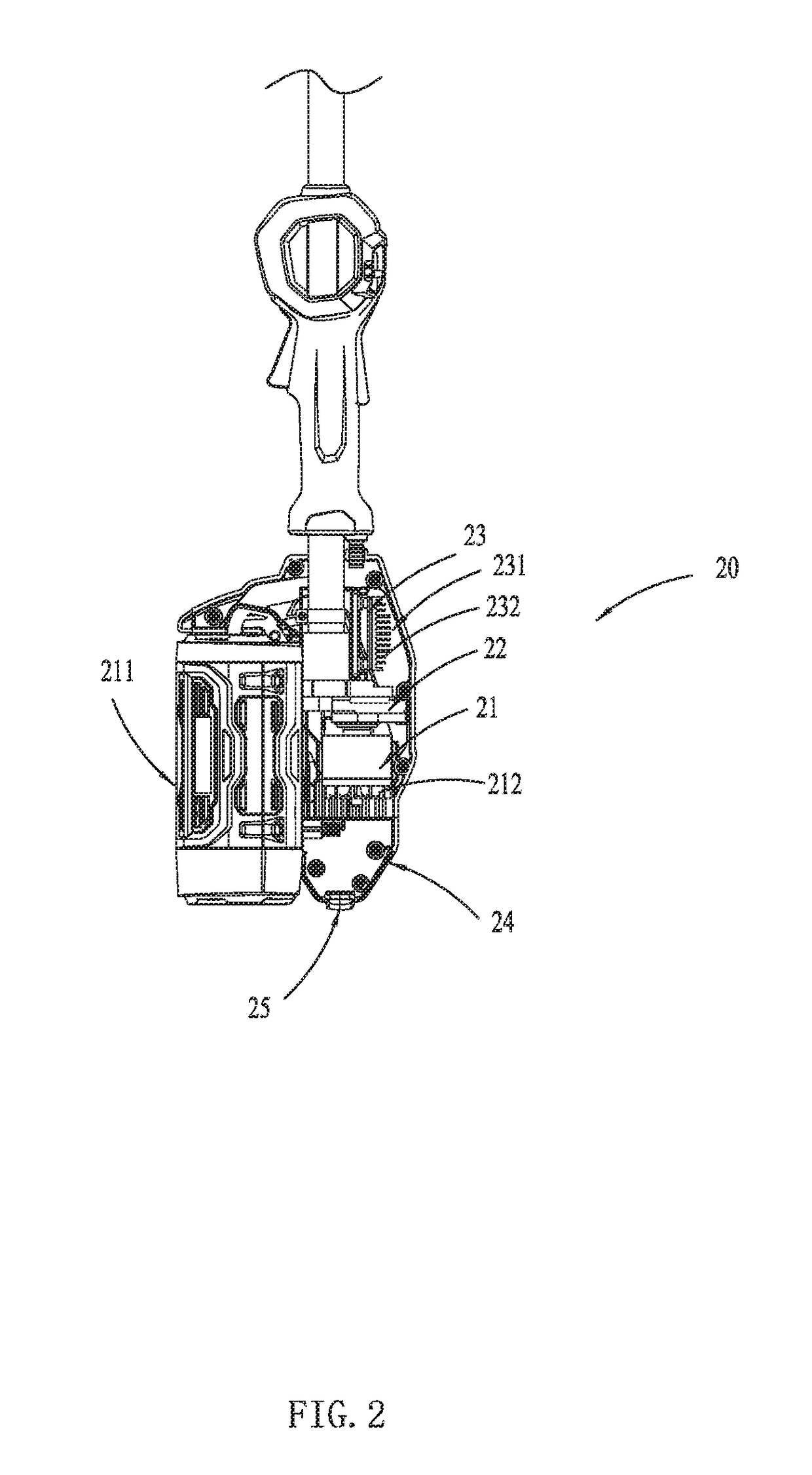
[0075]The powering device 20 is configured to provide a driving force to the working device 10. As illustrated in FIG. 2, the example power device 20 includes a motor 21, a tran...


PUM


Abstract

A handheld electric tool includes a working device for performing a function of the handheld electric tool, a powering device for provide a driving force to the working device, and a connecting device for connecting the working device and powering device. The powering device includes: an electric motor, a power housing having an air inlet and an air outlet, a transmission mechanism for transmitting power generated by the electric motor and a circuit board for controlling the electric motor, a fan can be driven by the electric motor to provide an airflow which flows from the air inlet to the air outlet. The circuit board, the transmission mechanism and the electric motor are disposed between the air inlet and the air outlet such that the airflow flows through the circuit board, the transmission mechanism and the electric motor successively. The handheld electric tool has excellent cooling effect.

Description

CROSS REFERENCE TO RELATED APPLICATION[0001]This application claims the benefit under 35 U.S.C. §119(a) of Chinese Patent Application No. CN 201510568374.8, filed on Sep. 8, 2015, Chinese Patent Application No. CN 201510996457.7, filed on Dec. 24, 2015, Chinese Patent Application No. CN 201510993197.8, filed on Dec. 24, 2015, Chinese Patent Application No. CN 201510992221.6, filed on Dec. 24, 2015, the disclosure of each is incorporated herein by reference in their entirety.FIELD OF THE DISCLOSURE[0002]The disclosure relates to a handheld electrical tool.BACKGROUND OF RELATED ART[0003]A handheld power tool includes a working device and a powering device. The powering device is for providing a driving force to the working device. When the powering device uses electricity as energy source, such handheld power tool can also be referred to as handheld electric tool. Commonly used handheld power tools are hedge trimmers, grass trimmers, pole saws, etc.[0004]Powering devices using electri...

Claims


Application Information

Patent Timeline
Patent Type & Authority Applications(United States)
IPC IPC(8): B25F5/00A01G3/06A01G3/08
CPCB25F5/008A01G3/062A01G3/086
Inventor FU, HUIXINGNIE, FANGJIEYAMAOKA, TOSHINARIDENG, FANGTIAN
Owner CHERVON HK LTD WANCHAI
Why Eureka
Try Eureka