Internal combustion engine

a combustion engine and internal combustion technology, applied in combustion engines, machines/engines, cylinders, etc., can solve problems such as difficult to create a strong tumble flow in the combustion chamber, and achieve the effect of strong tumble flow

Active Publication Date: 2017-03-09
TOYOTA JIDOSHA KK
View PDF30 Cites 3 Cited by
  • Summary
  • Abstract
  • Description
  • Claims
  • Application Information

AI Technical Summary

Benefits of technology

[0014]In an internal combustion engine according to the configuration described above, it is easy to cause the entire intake air (main flow and branch flow) flowing into the combustion chamber from the intake port to flow along the exhaust valve bottom surface. Then, after flowing along the exhaust valve bottom surface, the intake air flows along the inner peripheral surface of the cylinder. That is, it is possible to cause the intake air to flow along the combustion chamber wall surface so that it is possible to generate a strong tumble flow in the combustion chamber.

Problems solved by technology

Therefore, it may be difficult to create a strong tumble flow in the combustion chamber 510.

Method used


Image

  • Internal combustion engine
  • Internal combustion engine
  • Internal combustion engine

Examples


Embodiment Construction

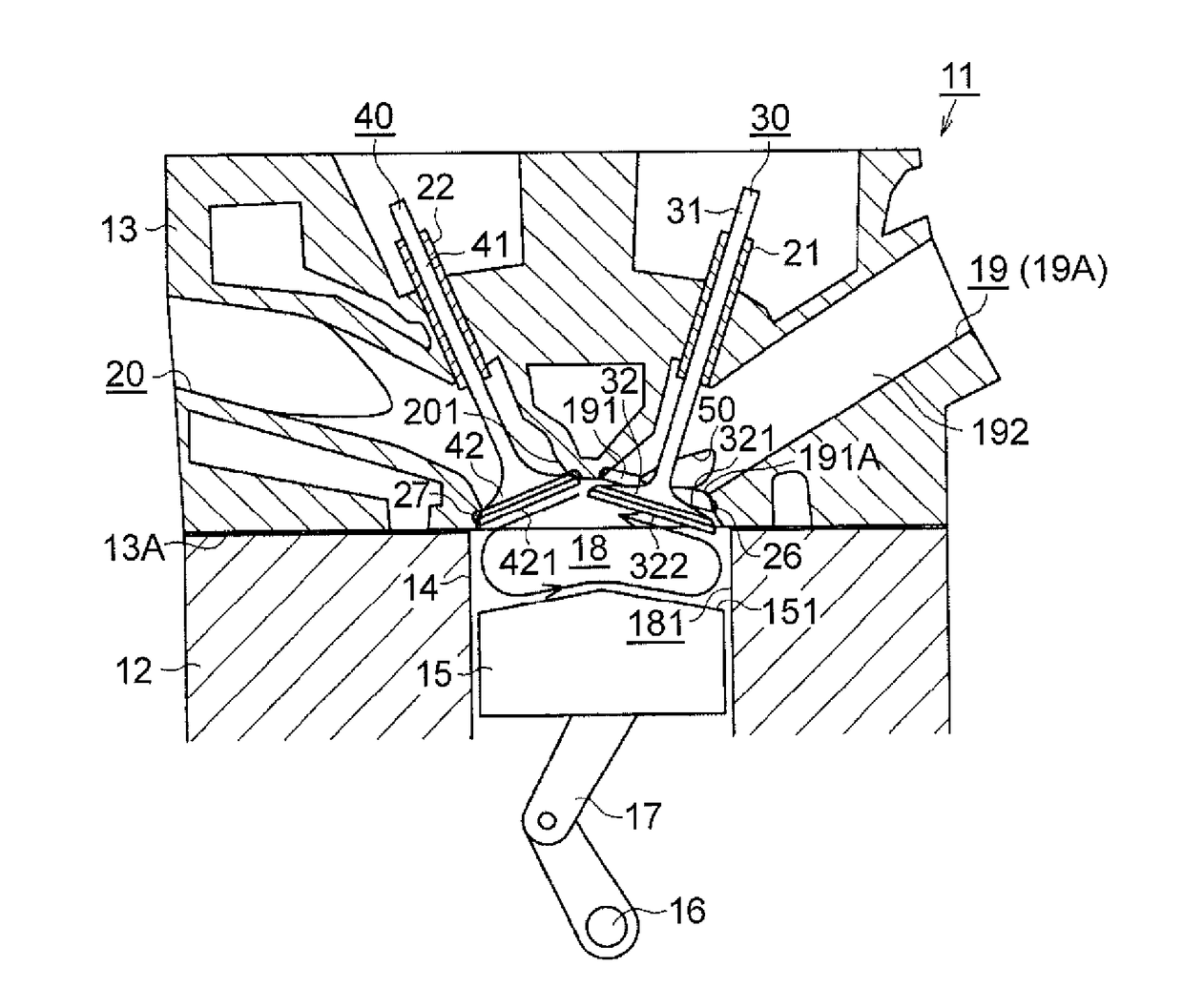
[0027]Hereinbelow, an embodiment of an internal combustion engine will be described with reference to FIGS. 1 to 10. As shown in FIG. 1, an internal combustion engine 11 of this embodiment includes a cylinder block 12 and a cylinder head 13 mounted on an upper portion in the figure of the cylinder block 12. In the cylinder head 13, its lower surface in the figure mounted on the cylinder block 12 will be referred to as a “mounting surface 13A”.

[0028]The internal combustion engine 11 includes a plurality of cylinders 14 and a piston 15 that reciprocates vertically in the figure is provided in each cylinder 14. An engine output shaft 16 extends in a direction perpendicular to the sheet surface. The engine output shaft 16 is connected to the pistons 15 via connecting rods 17. A combustion chamber 18 is formed between a top surface 151 of the piston 15 and the cylinder head 13. A mixture of fuel and intake air is burned in the combustion chamber 18. In this embodiment, a surface defining...


PUM


Abstract

An intake port of an internal combustion engine is connected to a combustion chamber and includes a connecting portion having a passage cross-sectional area that increases as the connecting portion approaches the combustion chamber, and an upstream portion connected to an upstream end of the connecting portion. The connecting portion is provided at its downstream end with a valve seat with which an umbrella part of an intake valve is brought into contact. At least one recess extending in an extending direction of the intake port and included in the connecting portion and the upstream portion is provided at least at one of two portions, the two portions located on both sides in an extending direction of an output shaft, of a peripheral surface of the intake port.

Description

INCORPORATION BY REFERENCE[0001]The disclosure of Japanese Patent Application No. 2015-176934 filed on Sep. 8, 2015 including the specification, drawings and abstract is incorporated herein by reference in its entirety.BACKGROUND[0002]1. Technical Field[0003]The disclosure relates to an internal combustion engine that introduces intake air into a combustion chamber through an intake port, thereby generating a tumble flow in the combustion chamber.[0004]2. Description of Related Art[0005]Japanese Patent Application Publication No. 2008-255860 (JP 2008-255860 A) discloses an internal combustion engine that generates a tumble flow in a combustion chamber. That is, as shown in FIG. 11, the intake air introduced into a combustion chamber 510 through an intake port 500 flows in a counterclockwise direction in the figure, thereby generating a tumble flow in the combustion chamber 510. A cylinder head 520 of this internal combustion engine is provided with a tubular valve guide 540 by which...

Claims


Application Information

Patent Timeline
Patent Type & Authority Applications(United States)
IPC IPC(8): F02B23/00
CPCF02B2275/48F02B23/00F02F1/42F02F1/4285F02B31/04F02F1/4235Y02T10/12
Inventor YAMAMOTO, YASUHIRONAGASAKI, TAKETOMIYAMOTO, YOSUKEMIYARA, NAOYUKITAKAGAWA, HAJIME
Owner TOYOTA JIDOSHA KK
Why Eureka
Try Eureka