Cylinder head for an internal combustion engine

a technology for internal combustion engines and cylinder heads, which is applied in the direction of engine starters, machines/engines, muscle operated starters, etc., can solve the problems of multiple pressing, reduced throughput, and strong flow cross section of the intake port, so as to prevent tension peaks in the cylinder head, reduce flow cross section, and strong tumble flow

Inactive Publication Date: 2005-04-19
AVL LIST GMBH
View PDF8 Cites 6 Cited by
  • Summary
  • Abstract
  • Description
  • Claims
  • Application Information

AI Technical Summary

Benefits of technology

[0005]It is the object of the present invention to further develop a cylinder head of the kind mentioned above in such a way that a strong tumble flow can be produced without any substantial reduction of the flow cross section of the intake port whilst preventing tension peaks in the cylinder head.

Problems solved by technology

A strong inclination of the central line of the flow of the intake port relative to the axis of the valve seat ring leads to the disadvantage however that the flow cross section of the intake port is strongly reduced, which has a disadvantageous effect especially in the full load range by a considerably reduced throughput.
This leads to multiple pressings and high mechanical stresses in this region.

Method used


Image

  • Cylinder head for an internal combustion engine
  • Cylinder head for an internal combustion engine

Examples


Embodiment Construction

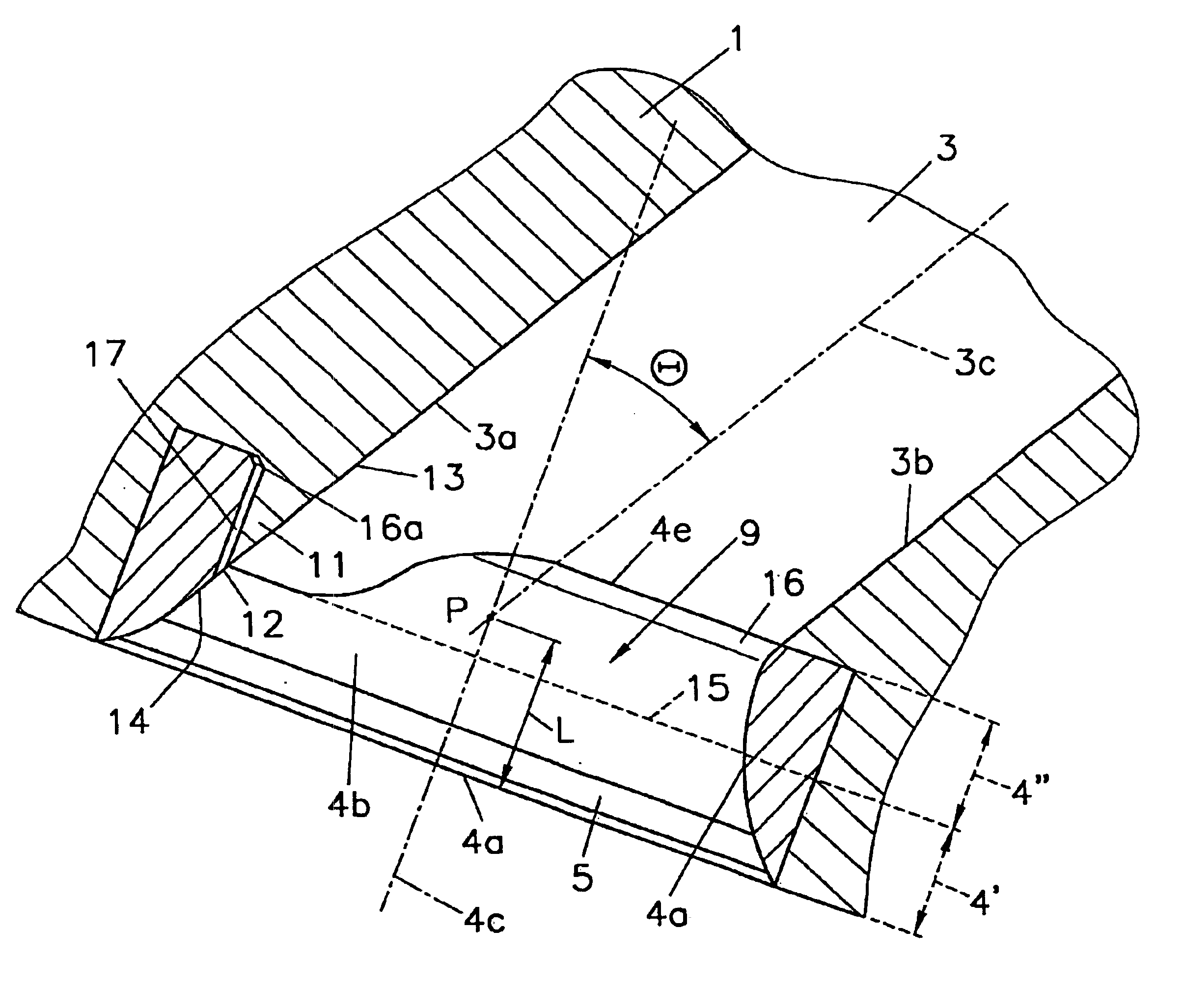
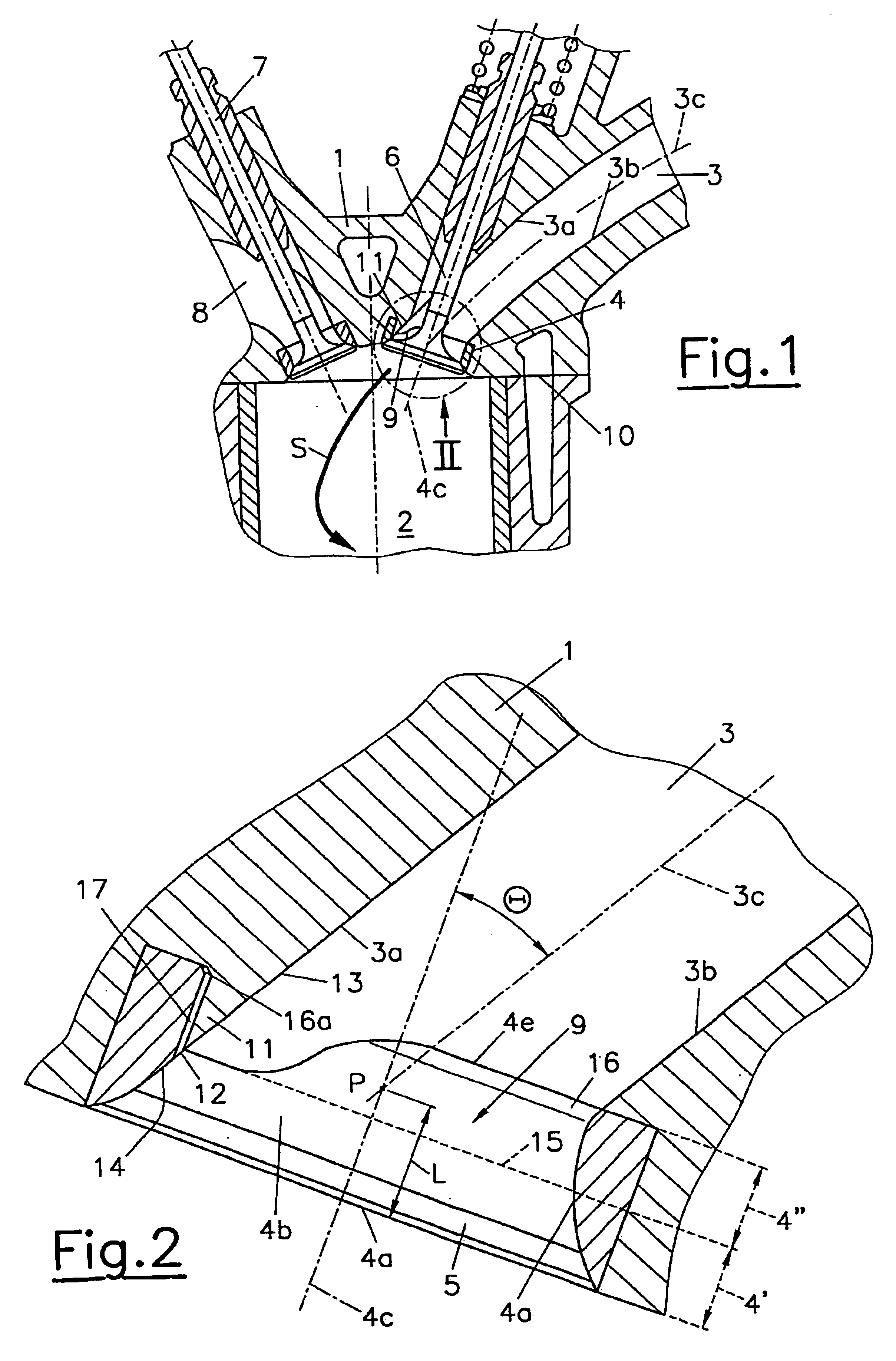
[0013]The cylinder head 1 comprises at least one intake port 3 producing a tumble flow S in the combustion chamber 2. A valve seat ring 4 is arranged in the cylinder head 1 in the region of the opening 9 of the intake port 3 into the combustion chamber 3. The valve seat ring 4 forms the valve seat 5 for the intake valve 6. An exhaust valve is designated with reference numeral 7 and is used for controlling an exhaust port 8. The wall region of intake port 3 which is the outside one relative to the tumble flow S is designated with reference numerals 3a. The inner wall region is designated with reference numeral 3b. When seen in a normal sectional view relative to the central line 3c of the port, the outer wall region 3a is spaced further away from the cylinder head plane 10 than the inner wall region 3b.

[0014]In order to produce the strongest possible tumble flow S in the combustion chamber 2, the cylinder head 1 is provided in the region of the opening 9 of the intake port 3 into th...


PUM


Abstract

The invention relates to a cylinder head (1) for an internal combustion engine with at least one inlet channel (3), which generates a swirling flow (S) in the combustion chamber (2), preferably curved in the direction of the swirling flow (S) with an external wall region (3a) and an internal wall region (3b) relative to the swirling flow (S). A valve seat ring (4) is arranged in the region of the opening (9) of the inlet channel (3) into the combustion chamber (2). According to the invention, a strong swirling flow (S) without significant reduction of the flow cross-section of the inlet channel (3) may be achieved whilst keeping the mechanical loading on the cylinder head to a minimum, whereby the external wall region (3a), in the region of the valve seat ring (4), is at least partly formed by a projection (11) of the cylinder head (1) within an internal surface (4a) of the valve seat ring (4), whereby the internal surface (4a) of the valve seat ring (4) extends beyond said projection (11).

Description

BACKGROUND OF THE INVENTION[0001]The invention relates to a cylinder head for an internal combustion engine with at least one intake port which generates a tumble flow in the combustion chamber, which channel is curved preferably in the direction of the tumble flow and comprises a wall region which is external relative to the tumble flow and an inner wall region, with a valve seat ring being arranged in the region of the opening of the intake port into the combustion chamber.[0002]Cylinder heads with intake ports producing a tumble flow are known from U.S. Pat. No. 5,640,941 A, U.S. Pat. No. 5,165,374 A, U.S. Pat. No. 5,359,972 A or GB 2 165 886 A. Especially in the partial load region it is possible to favorably influence the progress of the combustion by the tumble flow and thus the fuel consumption and emission formation, with the highest possible tumble flow being desirable.[0003]The amount of the tumble flow is relevantly determined by the position of the point of intersection ...

Claims


Application Information

Patent Timeline
Patent Type & Authority Patents(United States)
IPC IPC(8): F02B31/00F02F1/42F01L3/06
CPCF02B31/00F02F1/4235Y02T10/146Y02T10/12
Inventor LAIMBOCK, FRANZ
Owner AVL LIST GMBH
Why Eureka
Try Eureka