Aerial device that cooperates with an external projector to measure three-dimensional coordinates

a technology of three-dimensional coordinates and aerial devices, applied in the field of system for measuring three-dimensional (3d) coordinates, can solve problems such as lack of accuracy and detail

Active Publication Date: 2017-03-09
FARO TECH INC
View PDF2 Cites 86 Cited by
  • Summary
  • Abstract
  • Description
  • Claims
  • Application Information

AI Technical Summary

Problems solved by technology

A particular issue that may be encountered when using triangulation (which may further include videog...

Method used


Image

  • Aerial device that cooperates with an external projector to measure three-dimensional coordinates
  • Aerial device that cooperates with an external projector to measure three-dimensional coordinates
  • Aerial device that cooperates with an external projector to measure three-dimensional coordinates

Examples


Embodiment Construction

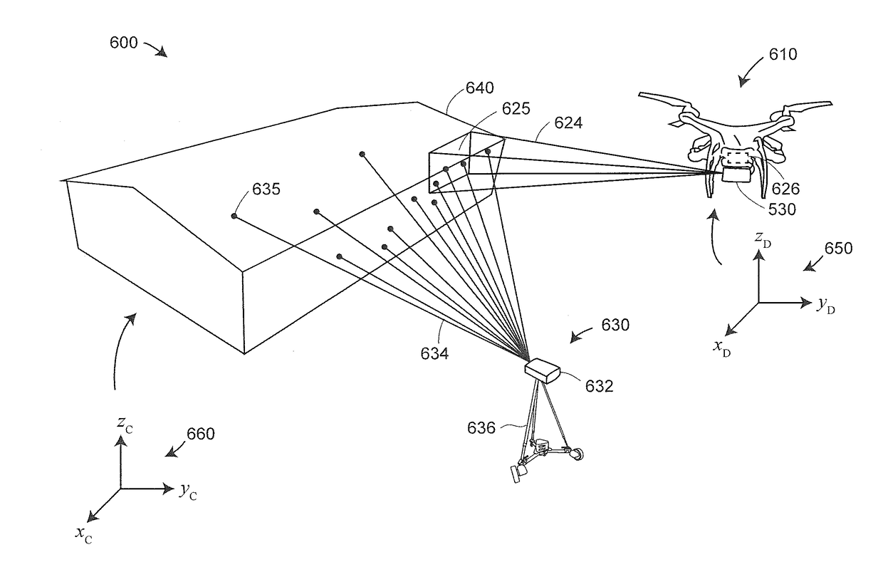
[0029]Embodiments of the present invention provide advantages in measuring large objects with 3D imagers, obtaining relatively high accuracy while providing color (texture) information.

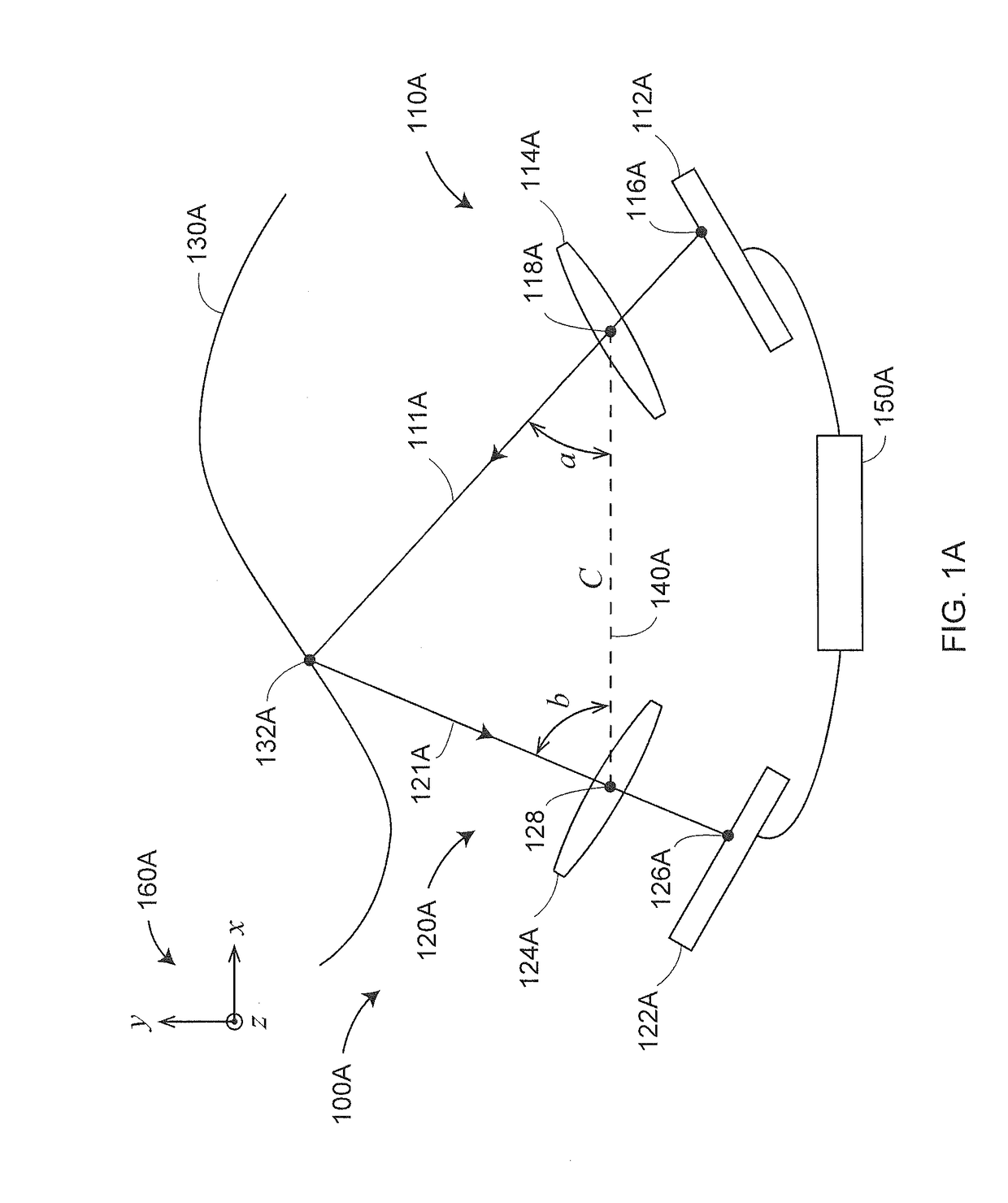
[0030]FIG. 1A shows a triangulation scanner (3D imager) 100A that projects a pattern of light over an area on a surface 130A. Another name for a structured light triangulation scanner is a 3D imager. The scanner 100A, which has a frame of reference 160A, includes a projector 110A and a camera 120A. The projector 110A includes an illuminated projector pattern generator 112A, a projector lens 114A, and a perspective center 118A through which a ray of light 111A emerges. The ray of light 111A emerges from a corrected point 116A having a corrected position on the pattern generator 112A. In an embodiment, the point 116A has been corrected to account for aberrations of the projector, including aberrations of the lens 114A, in order to cause the ray to pass through the perspective center 118A, thereby simpli...


PUM


Abstract

A three-dimensional (3D) coordinate measuring system includes an external projector that projects a pattern of light onto an object and an aerial drone attached to a 3D imaging device, the 3D imaging device and the external projector cooperating to obtain 3D coordinates of the object.

Description

CROSS-REFERENCE TO RELATED APPLICATIONS[0001]The present Application is a Nonprovisional Application of U.S. Provisional Application Ser. No. 62 / 215,978 filed on Sep. 9, 2015, and U.S. Provisional Application Serial No. 62 / 216,021 filed on Sep. 9, 2015, and also U.S. Provisional Application Ser. No. 62 / 216,027 filed on Sep. 9, 2015, the contents of all of which are incorporated herein by reference in their entirety.FIELD OF THE INVENTION[0002]The subject matter disclosed herein relates in general to system for measuring three-dimensional (3D) coordinates using a scanner device operated from a mover apparatus such as a drone.BACKGROUND OF THE INVENTION[0003]A 3D imager uses a triangulation method to measure the 3D coordinates of points on an object. The 3D imager usually includes a projector that projects onto a surface of the object either a pattern of light in a line or a pattern of light covering an area. A camera is coupled to the projector in a fixed relationship, for example, b...

Claims


Application Information

Patent Timeline
IPC IPC(8): G01B11/25
CPCG01B11/254G01B11/2513G01B11/24G01C15/002G01B11/2545B64U2101/30B64U20/87B64C39/024B64U10/13G01C15/00
Inventor HEIDEMANN, ROLFWOHLFELD, DENISBRIDGES, ROBERT E.KRAMER, HELMUT
Owner FARO TECH INC
Why Eureka
Try Eureka