Eureka AIR delivers breakthrough ideas for toughest innovation challenges, trusted by R&D personnel around the world.

Working vehicle

a technology for working vehicles and engines, applied in the field of working vehicles, can solve the problems of large engine compartment space, high temperature of diesel engines and exhaust gas purifying devices, and inability to operate comfortably in the cabin, so as to achieve convenient maintenance, large outer dimension, and the effect of facilitating maintenan

Active Publication Date: 2017-03-16
YANMAR POWER TECHNOLOGY CO LTD
View PDF38 Cites 6 Cited by
  • Summary
  • Abstract
  • Description
  • Claims
  • Application Information

AI Technical Summary

Benefits of technology

This patent is about a working vehicle that has an engine cover made of a porous plate on the rear lower sides of the hood. This helps to discharge heat outside while keeping the post-processing device hot enough for a good regeneration operation. When the hood is closed, there are also cooling mechanisms to bring in a lot of air to cool various components in the engine compartment. This helps to achieve a good heat balance and ensures that the engine runs efficiently.

Problems solved by technology

When the diesel engine provided with the exhaust gas treatment device described above is employed in the working vehicle such as a tractor, not only the diesel engine and the exhaust gas treatment device but also a radiator, a battery, and electronic components for the exhaust gas treatment device need to be crammed in a small and limited installation space.
In the installation space of the working vehicle, when the diesel engine is driven, the diesel engine emits heat, and thus temperature of the diesel engine itself as well as the exhaust gas purifying device becomes extremely high.
Furthermore, heating of a driver's seat, disposed on the rear side of the engine compartment, needs to be reduced or else, comfort of an operator in the cabin is compromised.
When the post-processing device such as the exhaust gas purifying device is installed, a large engine compartment space is required.

Method used


Image

  • Working vehicle
  • Working vehicle
  • Working vehicle

Examples


Embodiment Construction

[0050]An embodiment of the invention according to the present application is described below with reference to the drawings, with a tractor as an example of a working vehicle.

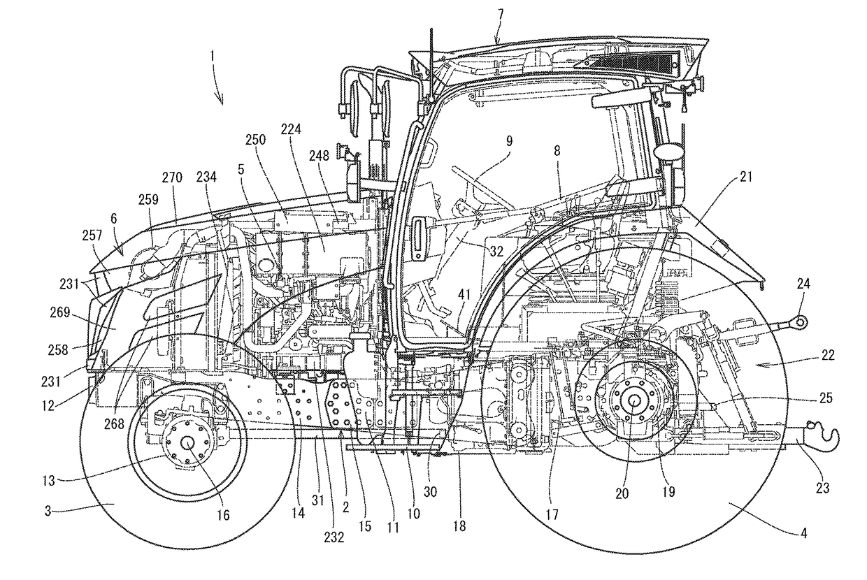
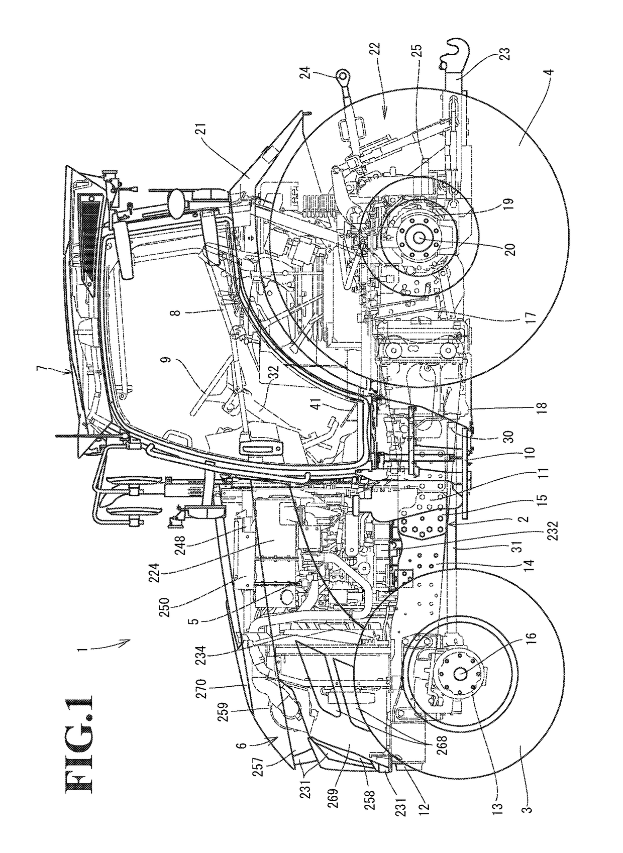
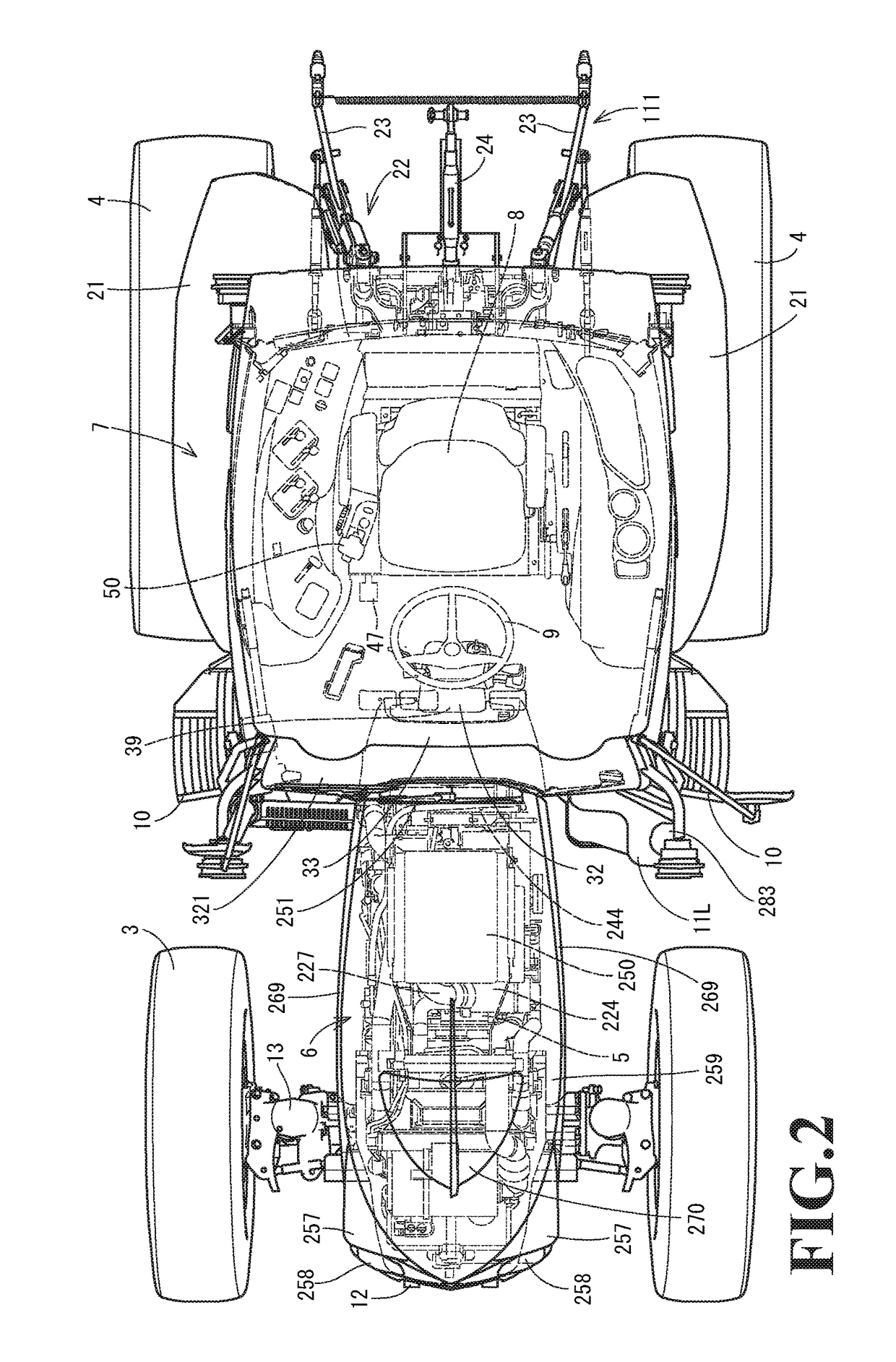
[0051]First of all, an overview of a tractor 1 is described with reference to FIG. 1 to FIG. 8. A traveling machine body 2 of the tractor 1 according to the embodiment is supported by a pair of left and right front wheels 3 and a pair of left and right rear wheels 4 as traveling units. A diesel engine 5 (hereinafter, simply referred to as an engine) of a common rail type, serving as a driving source, is installed in a front portion of the traveling machine body 2 and drives the rear wheels 4 and the front wheels 3 to make the tractor 1 travel forward and backward. The engine 5 is covered by a hood 6. A cabin 7 is disposed on an upper surface of the traveling machine body 2. The cabin 7 incorporates an operating seat 8 and a steering wheel (circular steering wheel) 9. A steering direction of the front wheels 3 m...


PUM


Abstract

The working vehicle includes an engine installed in a front portion of a traveling machine body, and a post-processing device configured to purify exhaust gas from the engine. The post-processing device is mounted on an upper side of the engine. The engine and the post-processing device are covered with a hood. A hood shield plate is disposed on a rear surface side of the hood and covers at least the post-processing device from a rear surface. A heat insulating layer is formed between an operating seat 8 disposed on a rear side of the hood and the hood shield plate.

Description

CROSS-REFERENCE TO RELATED APPLICATIONS[0001]The present application is a continuation application of International Application No. PCT / JP2015 / 063890, filed May 14, 2015, which claims priority to Japanese Patent Application No. 2014-111314, filed May 29, 2014. The contents of these applications are incorporated herein by reference in their entirety.BACKGROUND OF THE INVENTION[0002]The invention according to the present application relates to a working vehicle.[0003]Recently, enactment of strict emission regulation on diesel engines has led to increased demands for installing a post-processing device, such as an exhaust gas purifying device, in a farm work machine, a construction machine, a vessel, and the like including the diesel engine. The post-processing device executes purification processing for air pollutants in exhaust gas. In some conventional working vehicles, such as a tractor, the exhaust gas purifying device is disposed together with the diesel engine in an engine compa...

Claims


Application Information

Patent Timeline
Patent Type & Authority Applications(United States)
IPC IPC(8): B60K13/04B60K11/04B60K11/08B62D25/12
CPCB60K13/04B62D25/12B60K11/04B60Y2400/432B60Y2200/221B60Y2306/05B60K11/08B62D25/10B62D25/20B60R13/0876
Inventor KUROKAWA, YOSHIAKI
Owner YANMAR POWER TECHNOLOGY CO LTD
Why Eureka
Eureka Blog
Learn More