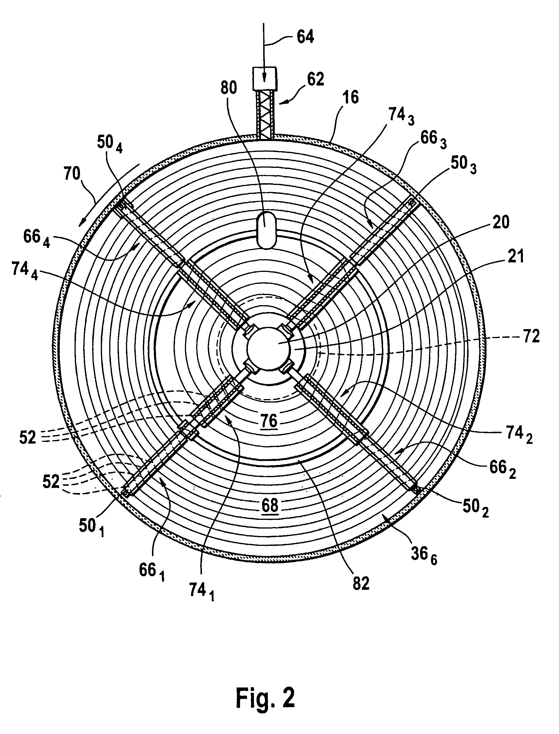
[0007] In accordance with the present invention, a method of operating multiple hearth furnace with a plurality of vertically aligned hearth floors, comprises in particular following steps. A first material is fed onto the uppermost hearth floor and moved over this uppermost hearth floor before it falls through a drop hole onto the next lower hearth floor. This first material is processed in this way from hearth floor to hearth floor down to the lowermost hearth floor. A second material is fed onto one of the hearth floors to be mixed into the first material. In accordance with an important aspect of the present invention, the second material is moved separately from the first material in a separate annular zone of the hearth floor onto which it is fed before it is mixed into the first material. It will be appreciated that this method allows to provide an efficient thermal preconditioning of the second material prior to mixing it into the first material without requiring any supplementary equipment therefore.
[0008] In a generally preferred implementation of the method, the second material is fed onto an outer annular zone of a hearth floor, and the first material is dropped from a higher hearth floor onto an inner annular zone of this hearth floor. The first material is then moved in the inner annular zone of the hearth floor, and the second material is moved in the outer annular zone surrounding the first material in the inner annular zone. It will be appreciated that this way of proceeding allows to easily feed the second material through a lateral outer wall of the furnace onto the respective hearth floor.
[0012] In an alternative implementation of the method in accordance with the present invention, the second material is fed onto an inner annular zone of a hearth floor and moved herein, and the first material is dropped onto an outer annular zone of the hearth floor and moved herein around the second material in the inner annular zone of the hearth floor. This implementation is of particular interest if the second material can be easily fed, e.g. by means of a cooled conveyor radially introduced into the hearth chamber or through a hollow central shaft of the multiple hearth furnace, onto the inner periphery of the inner annular zone.
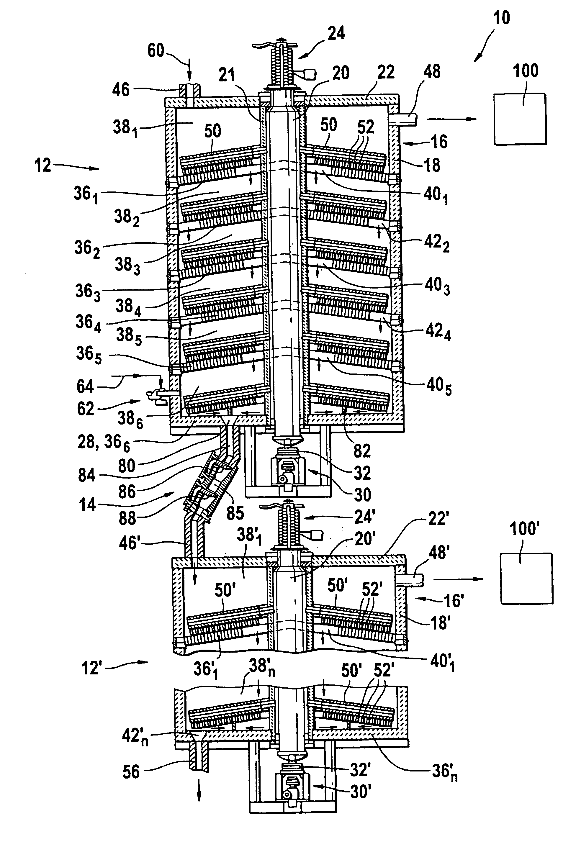
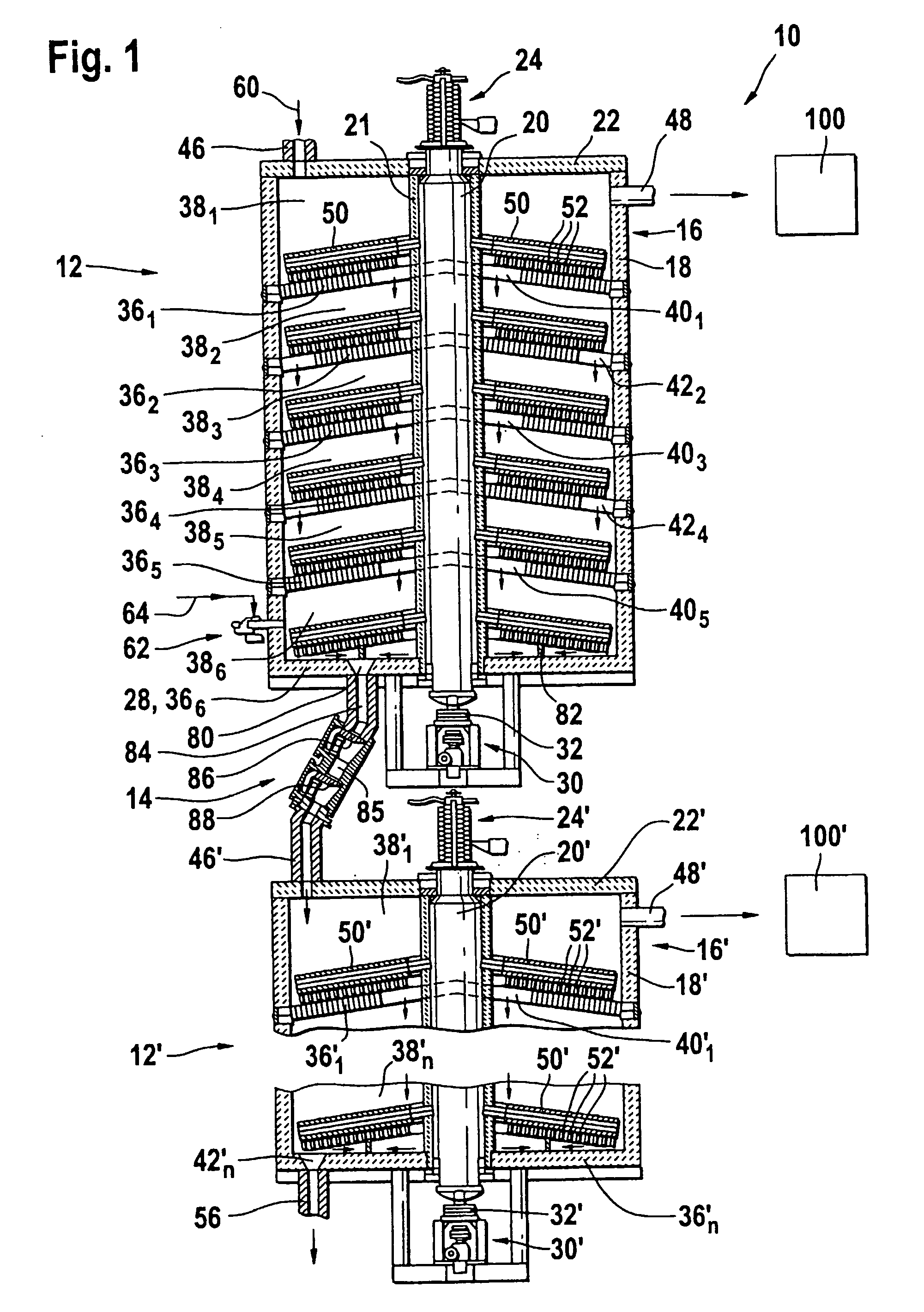
[0014] It will be appreciated that the above described method of operating a multiple hearth furnace can be advantageously used within the context of a process for recovering metals from dusts and sludges, including inter alia important amounts of iron,
zinc and lead. Such a process is advantageously carried out in a multiple hearth furnace comprising a first furnace stage and a second furnace stage. Separate furnace atmospheres prevail in each furnace stage, and each stage has a plurality of vertically aligned hearth floors. The first material, i.e. the material that is fed onto the uppermost hearth floor of the first furnace stage, is a material comprising the
metal oxides. The second material, that is the additional material that is fed onto one of the hearth floors, is a
coal with volatile constituents. The first material is first subjected to mainly endothermic preconditioning processes in the first furnace stage. The
coal is fed onto the lowermost hearth floor of the first furnace stage and moved thereon separately from the first material in a separate annular zone of this hearth floor, wherein most of its volatile constituents are driven off and burned in the first furnace stage. The preconditioned first material and the preconditioned
coal are then fed through at least one material lock onto the uppermost hearth floor of the second furnace stage and thoroughly mixed thereon, so that the
metal oxides are subjected to a reduction by the preconditioned coal. It will be appreciated that this method of operating the
double stage hearth furnace allows to substantially improve the
thermal balance of the process by using the
combustion energy of the volatile constituents of the coal for the endothermic processes in the first furnace stage. At the same time it helps to avoid a start of the exothermic reduction process in the first furnace stage, which would disturb the
separation result by reducing and evaporating e.g. the
zinc in the first furnace stage instead of the second furnace stage. Furthermore, the method warrants an excellent preconditioning of the coal for the reduction process in the second furnace stage.

