Working vehicle

a technology for working vehicles and vehicles, applied in the field of working vehicles, can solve the problems of hindering the operator entering the shape hindering the operator's entry and exiting the tractor, and the increase in the entire capacity of the fuel tank cannot be pursued, so as to achieve excellent heat balance, prevent heat from negatively affecting the outside of the engine room, and high temperature environment

Active Publication Date: 2017-01-19
YANMAR POWER TECHNOLOGY CO LTD
View PDF12 Cites 5 Cited by
  • Summary
  • Abstract
  • Description
  • Claims
  • Application Information

AI Technical Summary

Benefits of technology

[0013]According to the embodiment of the invention of the present application, the post-processing device is positioned on a rear inner side of the inclined upper surface side of the hood. Thus, a large space for accommodating the post-processing device can be formed in the hood. Furthermore, a space serving as a heat insulation layer can be formed between the heat shield plate and the hood. Thus, a high temperature environment can be achieved around the post-processing device while preventing heat from negatively affecting the outside of the engine room. All things considered, an excellent heat balance can be achieved in the hood. The driving shaft of the wiper is covered with the rear portion of the upper surface of the hood. Thus, rain drops can be prevented from directly coming into contact with the driving shaft and a driving mechanism of the wiper, and a better appearance of the working vehicle can be achieved.
[0014]The heat shield plate is disposed above the post-processing device so that the hood can be prevented from being heated by the heat discharged from the post-processing device and the engine. The space is formed between the hood and the heat shield plate so that the inner side of the engine room below the heat shield plate is thermally insulated from the outer air, whereby the post-processing device can operate in a high temperature environment. The heat from the engine room below the hood is shielded with the hood shield plate. Thus, the drivers' seat can be prevented from being heated by the heat discharged from the engine room. With the hood shield plate and the heat shield plate disposed with a gap in between, the heat is less likely to accumulate in the engine room. Thus, the post-processing device can be prevented from being negatively affected by its own heat or from negatively affecting the hood or the like by the heat discharged therefrom.
[0015]The heat from the engine room below the hood is shielded with the hood shield plate. Thus, the driver's seat can be prevented from being heated by the heat discharged from the engine room. Thus, the operator on the driver's seat can comfortably operate the vehicle without being negatively affected by the heat discharged from the engine and the post-processing device.

Problems solved by technology

In a working vehicle, such as a tractor employing a diesel engine including the exhaust gas treating device described above, not only the diesel engine and the exhaust gas treating device but also various parts need to be packed in a limited and small installation space.
The disposed position of the fuel tank is limited, and thus an increase in the entire capacity of the fuel tank cannot be pursued over a certain level, and can even lead to a shape hindering the operator entering and exiting the tractor.

Method used


Image

  • Working vehicle
  • Working vehicle
  • Working vehicle

Examples


Embodiment Construction

[0040]An embodiment of the invention of the present application is described with reference to the drawings with a tractor as an example of a working vehicle.

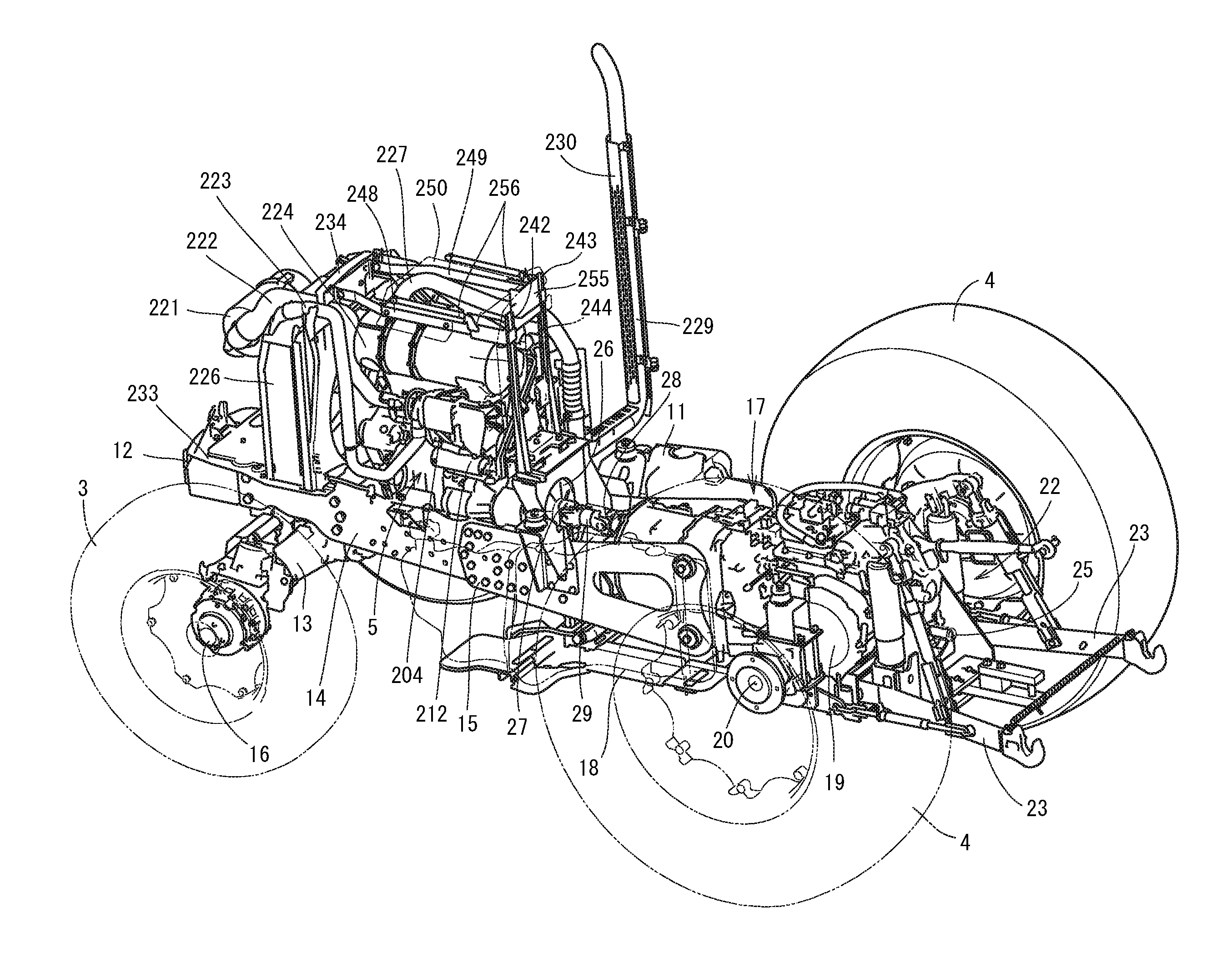
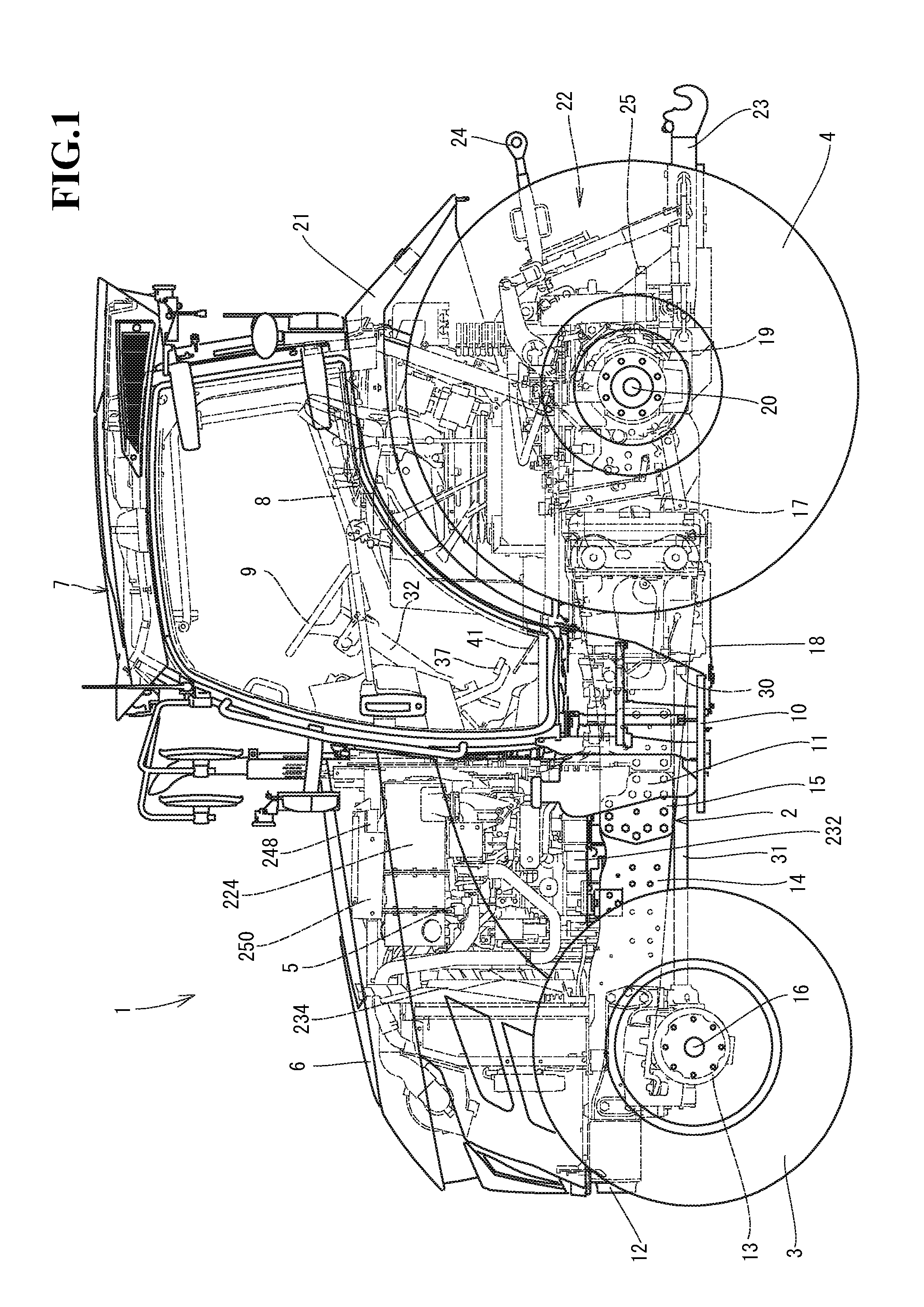
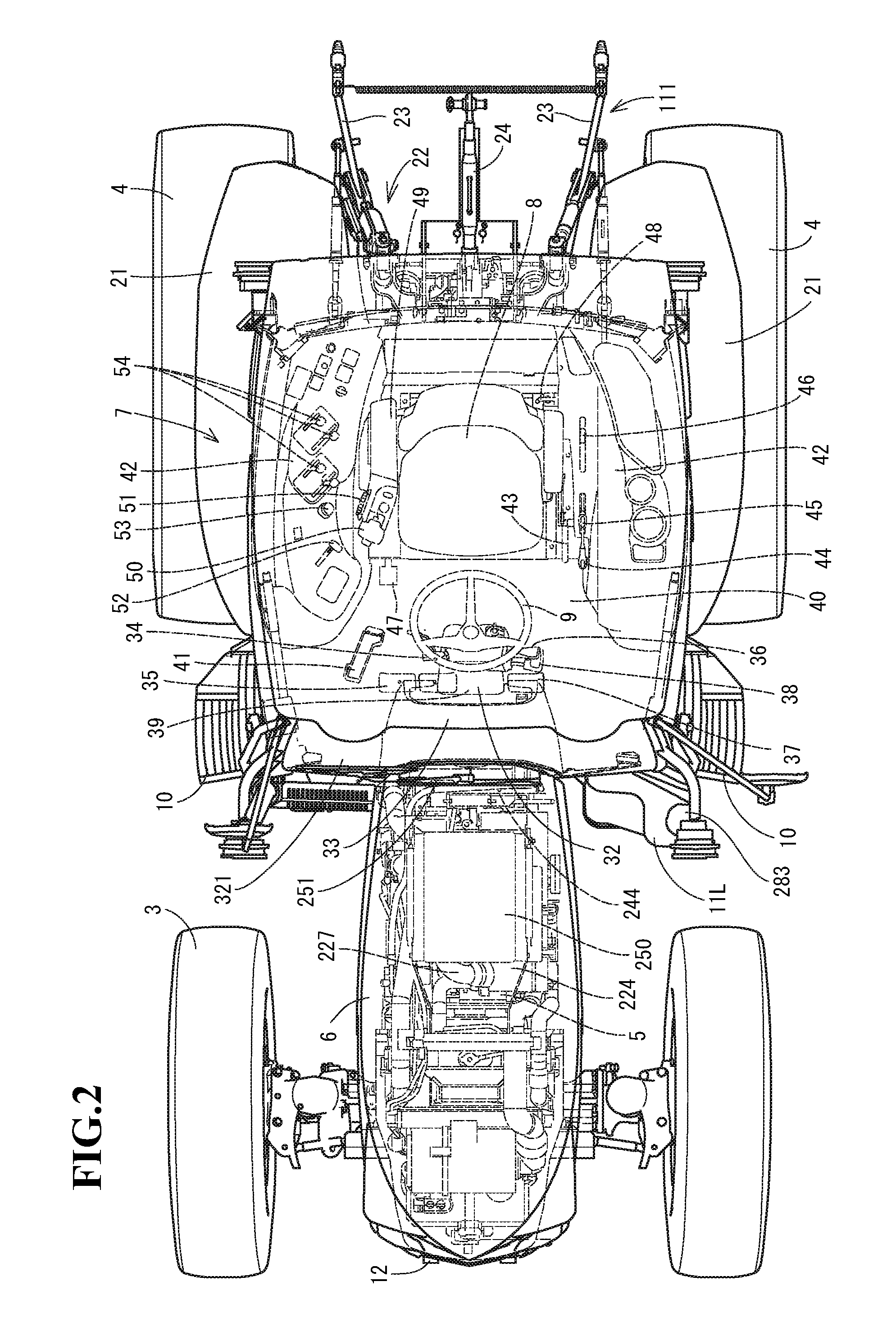
[0041]First of all, an overview of a tractor 1 is described with reference to FIGS. 1 to 11. A travelling vehicle 2 of the tractor 1 according to the embodiment is supported by a pair of left and right front wheels 3 and a pair of left and right rear wheels 4 serving as a travelling unit. The tractor 1 travels forward and backward when the front and the rear wheels 3 and 4 are driven by a common rail diesel engine 5 (hereinafter, simply referred to as an engine) serving as a source of driving force that is installed in a front portion of the travelling vehicle 2. The engine 5 is covered by a hood 6. A cabin 7 is disposed on an upper surface of the travelling vehicle 2, and incorporates a driver's seat 8 and a steering wheel (round steering wheel) 9. A steering operation on the steering wheel 9 turns a steering direction of the ...


PUM


Abstract

A working vehicle includes an engine mounted in a front portion of a travelling vehicle, and a post-processing device configured to purify exhaust gas from the engine. The engine and the post-processing device are covered with a hood. An upper surface side of the hood is inclined to extend diagonally upward from a front side to a rear side. The post-processing device is mounted on an upper side of the engine, and is positioned on a rear and inner side of the inclined upper surface side of the hood.

Description

CROSS-REFERENCE TO RELATED APPLICATIONS[0001]The present application is a continuation application of International Application No. PCT / JP2015 / 59517, filed Mar. 26, 2015, which claims priority to Japanese Patent Application No. 2014-69485, filed Mar. 28, 2014, and Japanese Patent Application No. 2014-69486, filed Mar. 28, 2014. The contents of these applications are incorporated herein by reference in their entirety.BACKGROUND OF THE INVENTION[0002]The present invention relates to a working vehicle.[0003]Recently, there has been a requirement for agricultural machines, construction machines, ships, and the like, on which a diesel engine is mounted, to have a post-processing device installed, due to a strict exhaust gas regulation applied to diesel engines. Such a post-processing device includes an exhaust gas purification device that performs purification processing for air pollutant in exhaust gas. Thus, some conventional working vehicles such as a tractor have an exhaust gas purif...

Claims


Application Information

Patent Timeline
Patent Type & Authority Applications(United States)
IPC IPC(8): B60K13/04B60R13/08B62D25/12B60S1/04
CPCB60K13/04B60S1/0402B60Y2200/221B62D25/12B60R13/083B60Y2410/114B62D25/10B60Y2200/415
Inventor KUROKAWA, YOSHIAKI
Owner YANMAR POWER TECHNOLOGY CO LTD
Why Eureka
Try Eureka