Method of manufacturing carbon nanotubes using electric arc discharge

a technology of carbon nanotubes and electric arcs, which is applied in the direction of carbon compounds, inorganic chemistry, nano-carbons, etc., can solve the problems of limited mass production, uneven cnt characteristics or shapes, and thermal electron emission, and achieve high oxidation peak temperature, high crystallinity, and high temperature to cnts

Active Publication Date: 2019-09-26
IND ACAD COOP GRP OF SEJONG UNIV
View PDF1 Cites 0 Cited by
  • Summary
  • Abstract
  • Description
  • Claims
  • Application Information

AI Technical Summary

Benefits of technology

[0012]According to the present inventive concept described above, MWCNTs having a high crystallinity and a high oxidation peak temperature can be obtained. In particular, the CNTs can be utilized as field emitters. The field emitters emit electrons upon application of a high voltage under a vacuum condition. During the emission of electrons, a large amount of current flows through the MWCNTs, which are emitters, and Joule heat is generated, thereby causing a high temperature to the CNTs. Also, the electric fields are concentrated at the ends of the CNT emitters, so that the electrostatic force acts strongly on them. In an environment of high temperature and strong electrostatic force, low crystallinity regions of CNTs can be damaged and cut. When a strong electric field is applied to the ends of the CNTs in a high temperature environment, the carbon atoms at the tube ends may evaporate and the CNTs may be damaged. When a small amount of oxidizing gas exists in a high temperature environment, CNTs having low oxidation peak temperatures can be easily oxidized and cannot act as the field emitters. In the present inventive concept, MWCNTs have high crystallinity and have a high oxidation peak temperature that can withstand such a high temperature environment.
[0013]In addition, high-quality CNTs can be obtained through low-cost synthesis gas using N2 and O2 gases.

Problems solved by technology

Further, a large amount of thermal electrons are emitted from the cathode and flows into the anode.
The chemical vapor deposition method is suitable to mass production, but when the gas flow rate is uneven in the reaction chamber, CNTs having uneven characteristics or shapes are synthesized.
In addition, when the laser vapor deposition method is used, the CNTs having high purity can be obtained, but mass production is limited.
For example, when a chemical vapor deposition method is used, CNTs having high crystallinity cannot be obtained due to a low synthesis temperature.

Method used


Image

  • Method of manufacturing carbon nanotubes using electric arc discharge
  • Method of manufacturing carbon nanotubes using electric arc discharge
  • Method of manufacturing carbon nanotubes using electric arc discharge

Examples


embodiment

[0028]FIG. 1 is a schematic view to explain manufacturing CNTs according to a preferred embodiment of the present inventive concept.

[0029]Referring to FIG. 1, a cathode 110 and an anode 120 are provided in a chamber.

[0030]The graphite used as the cathode 110 preferably has a cubic shape and is configured to synthesize CNTs on four surfaces of the graphite cube. Particularly, it is preferable to synthesize CNTs on one of the four surfaces of the graphite cube used as the cathode 110, then to terminate the CNT synthesis, and then to rotate to the next surface to synthesize the CNTs again. The graphite used for the cathode 110 is pure graphite G347 having an oxidation temperature of 735.3° C. and a crystalline evaluation index IG / ID of 1.5. A He—Ne laser having a wavelength of 633 nm is used for the crystallization evaluation. IG in the crystalline evaluation index IG / ID is the intensity of a peak that is generated around 1580 cm−1 by an in-plane phonon mode with a momentum of zero at ...

production example 1

sing Synthesis Gas

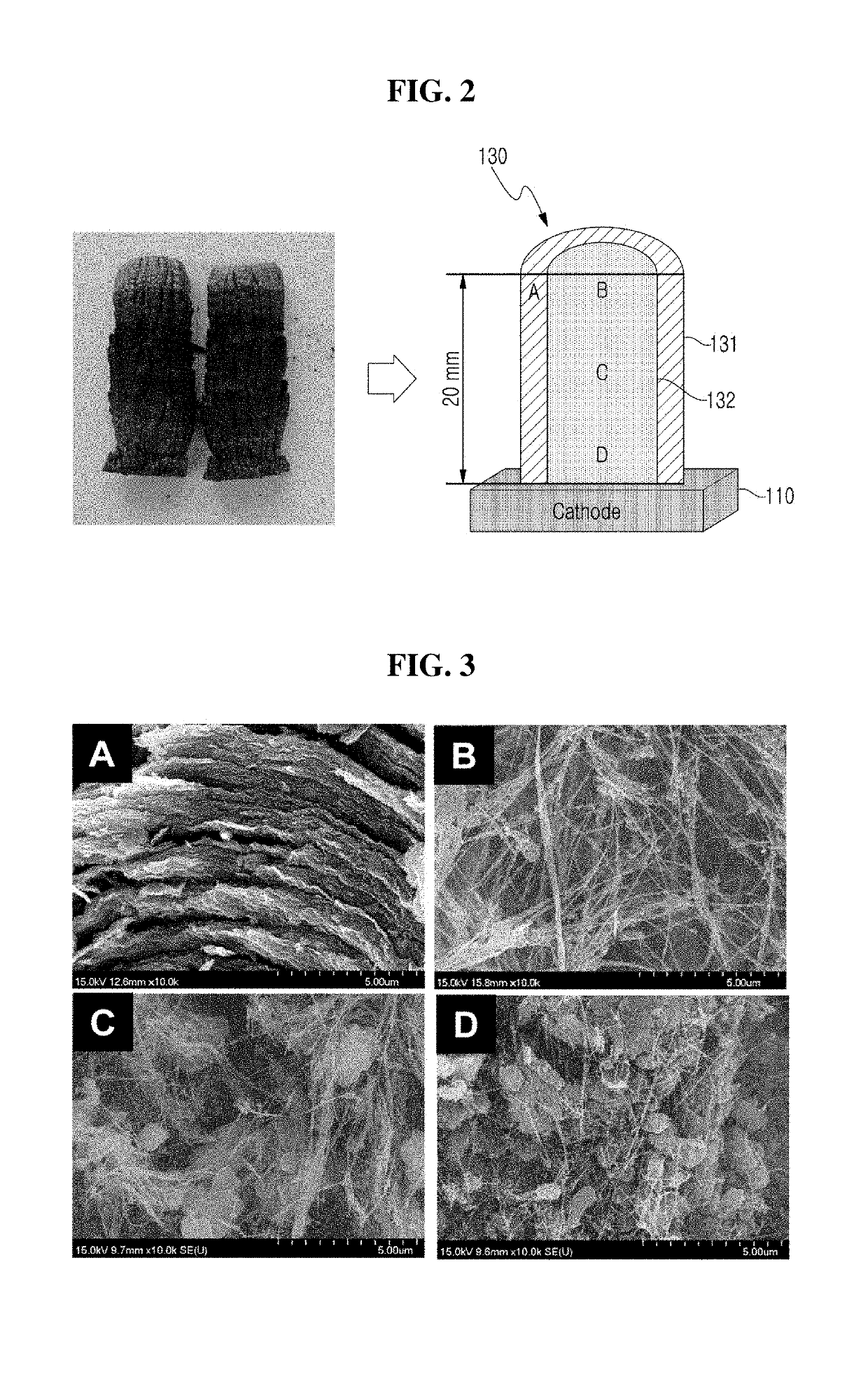
[0036]FIG. 2 is a digital camera image and a cross-sectional schematic view of CNT aggregate manufactured according to Production Example 1 of the present inventive concept.

[0037]Referring to FIG. 2, a pure graphite G347 rod having a length of 150 mm and a diameter of 8 mm is used as an anode, and a pure graphite G347 cube having a size of 100 mm×100 mm×100 mm is used as a cathode 110. The distance between the anode and the cathode 110 is kept constant at about 2 mm

[0038]A voltage between both electrodes is set to 20V to 25V, and the arc discharge is generated in a constant current mode of 80 A. During the arc discharge, the synthesis gas contains N2 and O2, the partial pressure ratio of the supplied N2 gas and the O2 gas is 9:1, and the chamber pressure of 60 torr is maintained. Arc discharge synthesis of CNTs is performed for 10 minutes.

[0039]When an arc discharge is generated between both electrodes by a voltage applied as described, carbon particles produced fr...

production example 2

Pressure Condition For Synthesis Of CNTs Using Arc Discharge In Air

[0055]FIG. 6 is SEM images showing CNTs manufactured by controlling the pressure of synthesis gas in a chamber according to Production Example 2 of the present inventive concept.

[0056]The CNTs shown in FIG. 6 are synthesized using the same graphite material for the cathode and the anode, and the same distance between both electrodes disclosed in FIG. 2. However, the chamber pressure of air is changed from 60 torr to 180 torr. In this production example, the crystallinity of the CNTs is evaluated according to the change of chamber pressure. Accordingly, it is possible to set an optimal chamber pressure in the present inventive concept.

[0057]Referring to FIG. 6, a pure graphite G347 rod having a length of 150 mm and a diameter of 8 mm is used as an anode, and a pure graphite G347 cube having a size of 100 mm×100 mm×100 mm is used as a cathode. The distance between the anode and the cathode is kept constant at about 2 m...


PUM


Abstract

Disclosed is a method for producing CNTs by an electric arc discharge method. The synthesis gas for the arc discharge includes nitrogen and oxygen gases. The oxygen gas in the synthesis gas is converted to reactive oxygen species by the arc discharge and chemically reacts with amorphous carbon. Accordingly, the formation of amorphous carbon is suppressed when CNTs are formed on the cathode, and thus, high crystallinity of CNTs can be secured.

Description

TECHNICAL FILED[0001]The present inventive concept relates to a method of manufacturing carbon nanotubes, and more particularly, to a method of manufacturing multi-walled carbon nanotubes using electric arc discharge.BACKGROUND ART[0002]Carbon nanotubes (CNTs) have a tubular structure composed of hexagons of carbon and have diameter of several nanometers and length of several tens of micrometers. CNTs have high aspect ratios because of their extremely large length-to-diameter ratios, high electrical conductivity, excellent thermal stability and chemical stability.[0003]CNTs have walls made of graphitic sheets. According to the number of walls, they can be divided into single-walled, double-walled and multi-walled CNTs and be manufactured by various synthesis methods. Methods for synthesizing CNTs include electric arc discharge, laser vapor deposition and chemical vapor deposition.[0004]The electric arc discharge method is a method of synthesizing CNTs using electric arc discharge. T...

Claims


Application Information

Patent Timeline
Patent Type & Authority Applications(United States)
IPC IPC(8): C01B32/16
CPCC01B32/16C01B2202/20
Inventor LEE, NAE SUNGSHIN, TAE HUN
Owner IND ACAD COOP GRP OF SEJONG UNIV
Why Eureka
Try Eureka