Methods of connecting testing equipment to a missile system

Active Publication Date: 2017-03-16
THE BOEING CO
View PDF5 Cites 4 Cited by
  • Summary
  • Abstract
  • Description
  • Claims
  • Application Information

AI Technical Summary

Benefits of technology

[0005]A need exists for a smaller and lighter missile system that includes testing equipment. Further, a need exists fo

Problems solved by technology

Notably, however, the separate and distinct wall of the instrumentation stage adds size and weight to the missile system, which may cause the missile system to operate in a different manner than a missile system without such testing equipment.
Moreover, connect

Method used


Image

  • Methods of connecting testing equipment to a missile system
  • Methods of connecting testing equipment to a missile system
  • Methods of connecting testing equipment to a missile system

Examples


Example

[0021]The foregoing summary, as well as the following detailed description of certain embodiments will be better understood when read in conjunction with the appended drawings. As used herein, an element or step recited in the singular and preceded by the word “a” or “an” should be understood as not necessarily excluding the plural of the elements or steps. Further, references to “one embodiment” are not intended to be interpreted as excluding the existence of additional embodiments that also incorporate the recited features. Moreover, unless explicitly stated to the contrary, embodiments “comprising” or “having” an element or a plurality of elements having a particular condition may include additional elements not having that condition.

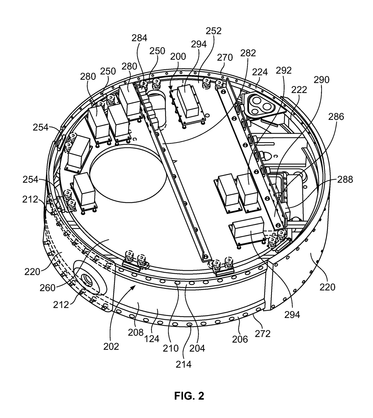
[0022]Certain embodiments of the present disclosure provide a method of mounting a secondary component or structure (such as an instrumentation platform) to a bolted interface that that may join adjacent primary components or structures together. The...


PUM


Abstract

A missile system includes a plurality of components, and a testing instrumentation platform secured within at least one of the plurality of components. The testing instrumentation platform is secured within the component(s) through at least one platform supporting adapter assembly. The platform supporting adapter assembly may include an adapter having a planar panel that supports one or more fasteners. The fastener(s) are configured to securely connect to a portion of a base of the testing instrumentation platform. At least one through-hole may be formed through a portion of the adapter. At least one tapered bolt is configured to be securely retained within the through-hole(s). The tapered bolt(s) securely connects the adapter to the component(s).

Description

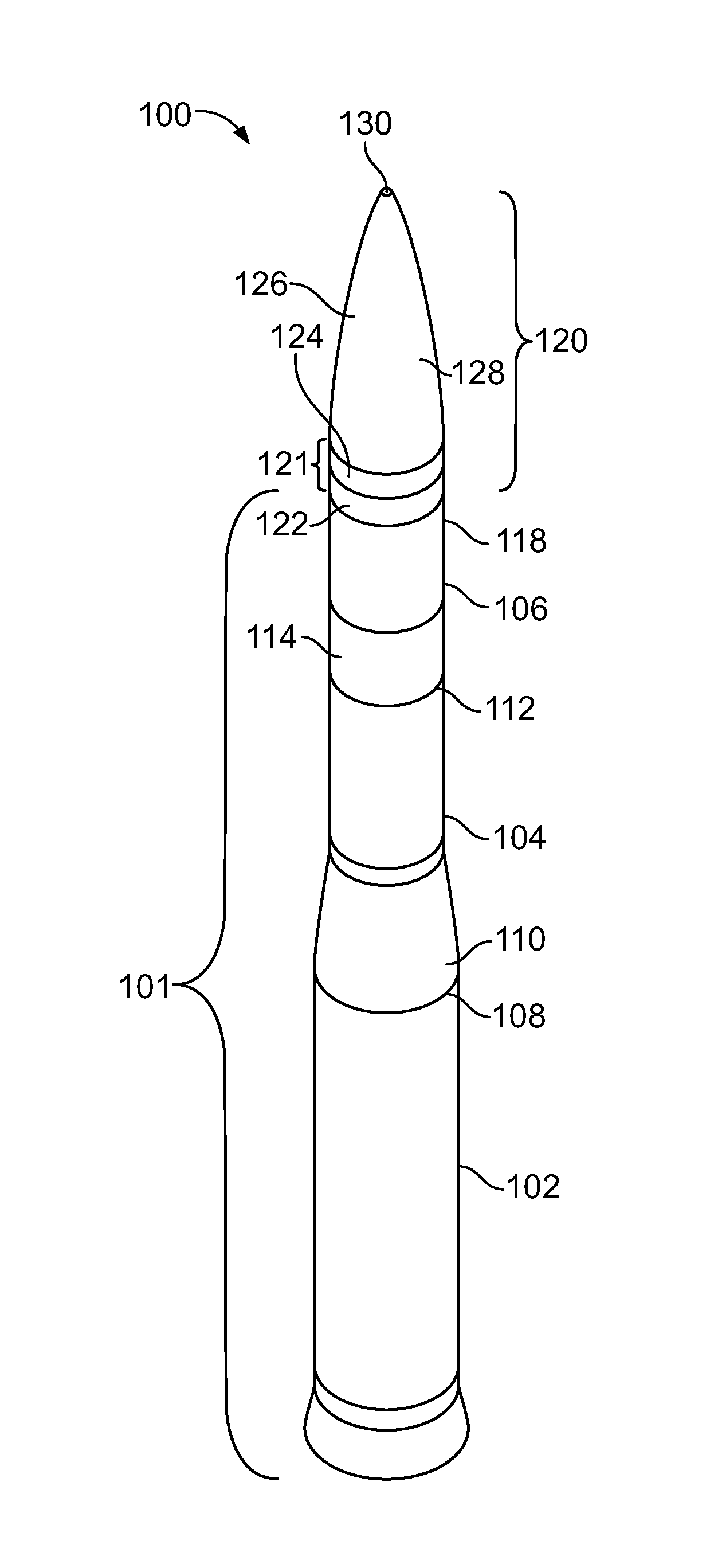
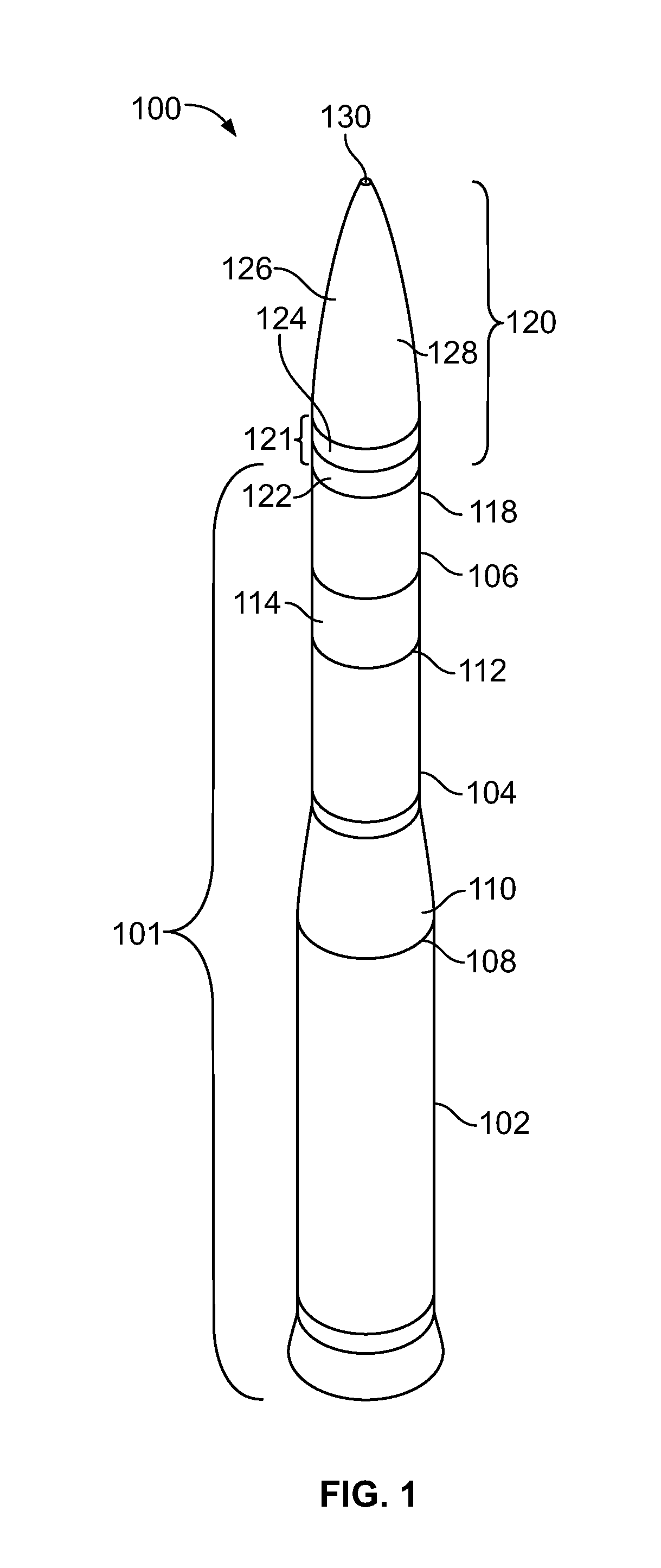
FIELD OF THE DISCLOSURE[0001]Embodiments of the present disclosure generally relate to methods of connecting testing equipment to a missile system, such as through one or more platform supporting adapter assemblies.BACKGROUND OF THE DISCLOSURE[0002]A known missile system includes a plurality of rocket or booster stages that are used to power the missile system into and / or above the atmosphere. For example, a first stage is activated to launch the missile system out of a silo. After a first time period after the launch (such as sixty seconds), the first stage separates from the missile system and falls back to Earth. As the first stage separates, a second stage activates. After a second time period after launch, the second stage separates and falls back to Earth, while a third stage activates. After a third time period after launch, the third stage deactivates, and a post-boost vehicle separates from the third stage. The post-boost vehicle maneuvers and prepares a re-entry system (RS...

Claims


Application Information

Patent Timeline
IPC IPC(8): F41G7/00
CPCF41G7/001F42B15/01F42B35/00
Inventor DOMINGUEZ, KEVIN
Owner THE BOEING CO
Why Eureka
Try Eureka