Image heating device and heater used for image heating device

a heating device and heater technology, applied in the field of image heating devices, can solve the problems of individual parts of the heater, non-uniform temperature distribution of the heater, and high-temperature offset of the toner, so as to prevent the effect of non-uniform temperature distribution

Active Publication Date: 2017-03-16
CANON KK
View PDF0 Cites 18 Cited by
  • Summary
  • Abstract
  • Description
  • Claims
  • Application Information

AI Technical Summary

Benefits of technology

[0007]In one embodiment, the invention provides a heater and an image heating device that prevent non-uniformity of temperature distribution.

Problems solved by technology

If the temperature of the sheet non-passing portion becomes too high, individual parts in the device may be damaged, or if printing is performed by using large-sized paper while the temperature rise in the sheet non-passing portion is generated, high-temperature offset of toner may occur to the film in a region corresponding to the sheet non-passing portion of the small-sized paper.
Meanwhile, a conductive member for supplying power is connected to the heater, and temperature distribution of the heater is considered to be non-uniform due to heat radiation from the conductive member and an electrode to which the conductive member is connected.

Method used


Image

  • Image heating device and heater used for image heating device
  • Image heating device and heater used for image heating device
  • Image heating device and heater used for image heating device

Examples


exemplary embodiment 1

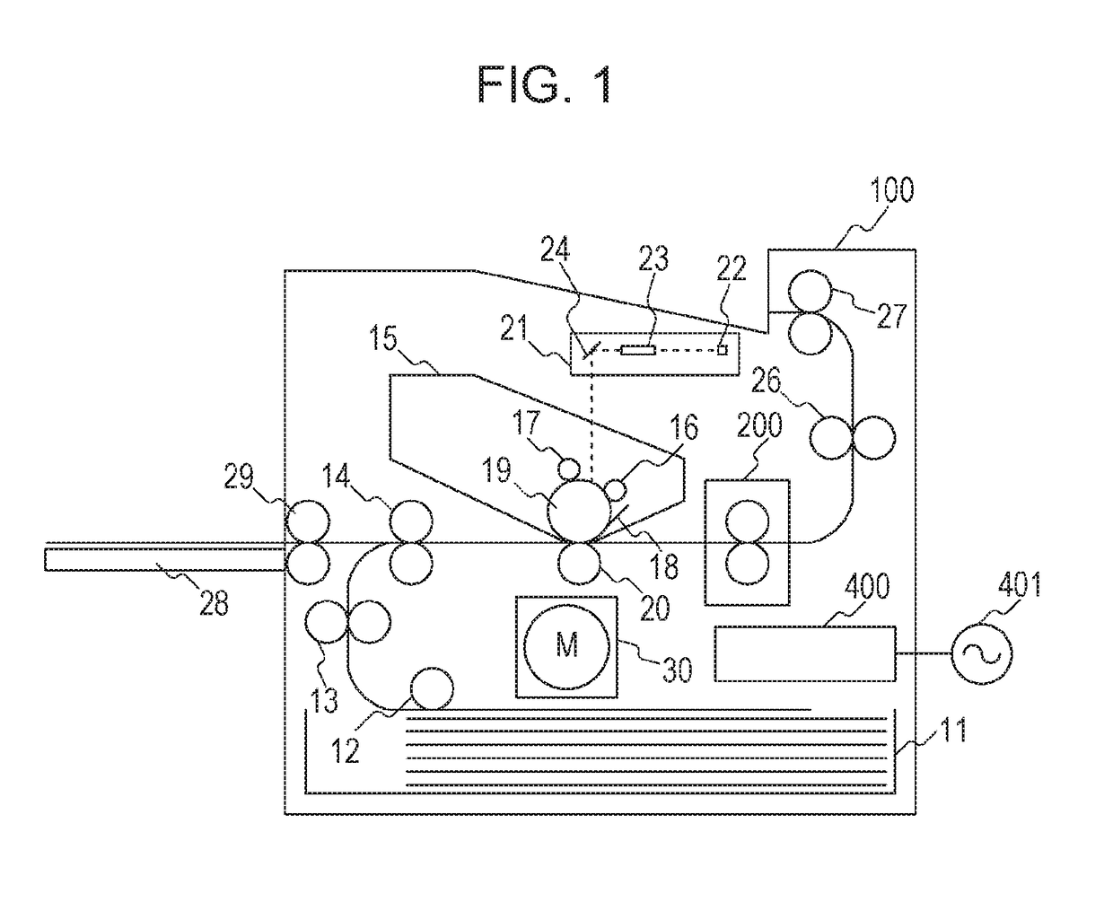
[0018]FIG. 1 is a cross-sectional view of a laser printer (image forming apparatus) 100 using an electrophotographic recording technique. When a print signal generates, a scanner unit 21 emits laser beam modulated depending on image information, and scans a photosensitive member 19 which is charged to a predetermined polarity by a charging roller 16. As a result, an electrostatic latent image is formed on the photosensitive member 19. Toner is supplied to this electrostatic latent image from a developing device 17, so that a toner image depending on the image information is formed on the photosensitive member 19. On the other hand, recording sheets (recording material) P stacked in a sheet supplying cassette 11 are fed one by one by a pick-up roller 12, and then is conveyed toward a registration roller pair 14 by a roller pair 13. Further, the recording sheet P is conveyed to a transfer position from the registration roller pair 14 in synchronism with timing when the toner image on ...

exemplary embodiment 2

[0060]A heater 600 in which arrangement of electrodes in a heat generating region is considered will be described in the present exemplary embodiment. The same reference signs will be assigned to similar configurations to those of the exemplary embodiment 1 and description thereof will be omitted.

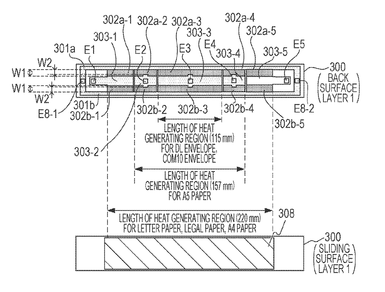
[0061]FIGS. 6A to 6C illustrate the heater 600 in the present exemplary embodiment. As illustrated in FIG. 6A, the electrode E3 is arranged to have lengths L1 and L2 from the electrode E8-1 and the electrode E8-2, respectively. The lengths L1 and L2 are not always set to be the same, and may be set to be different depending on, for example, arrangement of thermistors and the safety element 212. There is a relationship of the length L1>the length L2 in the heater 600.

[0062]A current path from the electrode E3 to the electrode E8-1 and the electrode E8-2 will be described with reference to FIG. 6B. Here, description will be given by dividing a heat generating block 602-3 of FIG. 6A into four ...


PUM


Abstract

A heater of the invention includes a substrate; a first conductive element and a second conductive element which are provided on the substrate along a longitudinal direction of the substrate; a heat generating element which is provided between the first conductive element and the second conductive element and generates heat with power supplied via the first conductive element and the second conductive element; and an electrode to which a conductive member for supplying power is connected, in which a heat generation amount of a region corresponding to a position at which an electrode of the heat generating element is provided is set to be greater than a heat generation amount of other regions.

Description

BACKGROUND OF THE INVENTION[0001]Field of the Invention[0002]The invention relates to an image heating device such as a fixing unit mounted in an image forming apparatus of an electrophotographic recording type, such as a copier or a printer, or a glossing device for improving a toner image in gloss by heating a fixed toner image on a recording material again. The invention also relates to a heater used for the image heating device.[0003]Description of the Related Art[0004]As an image heating device, there is a device having a cylindrical film, a heater in contact with an inner surface of the film, and a roller forming a nip portion via the film together with the heater. When an image forming apparatus provided with such an image heating device performs continuous printing using small-sized paper, a phenomenon occurs in which temperature of a region through which the paper does not pass in a longitudinal direction of the nip portion gently increases (temperature rise in a sheet non-...

Claims


Application Information

Patent Timeline
Patent Type & Authority Applications(United States)
IPC IPC(8): H05B3/00
CPCG03G15/2053G03G15/2042
Inventor OGURA, RYOTANISHIKATA, KAZUSHIHISANO, MASATOINUI, FUMIKIKUDO, KAZUHIDE
Owner CANON KK
Why Eureka
Try Eureka