
Cooling device for transition area of smelting reduction furnace

A technology of cooling device and reduction furnace, applied in furnace cooling, furnace, charge and other directions, can solve the problem that the refractory layer cannot be cooled in time and so on

Pending Publication Date: 2021-09-14
SHANDONG MOLONG PETROLEUM MACHINERY
View PDF7 Cites 1 Cited by
  • Summary
  • Abstract
  • Description
  • Claims
  • Application Information

AI Technical Summary

Problems solved by technology

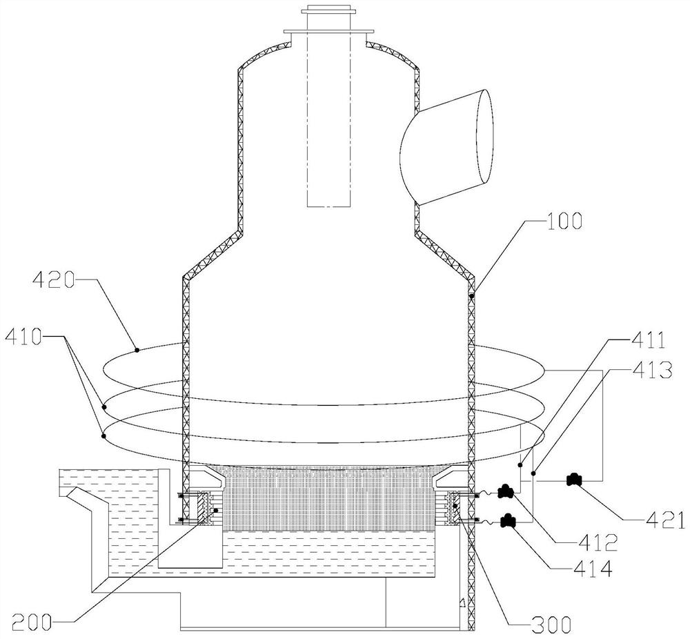
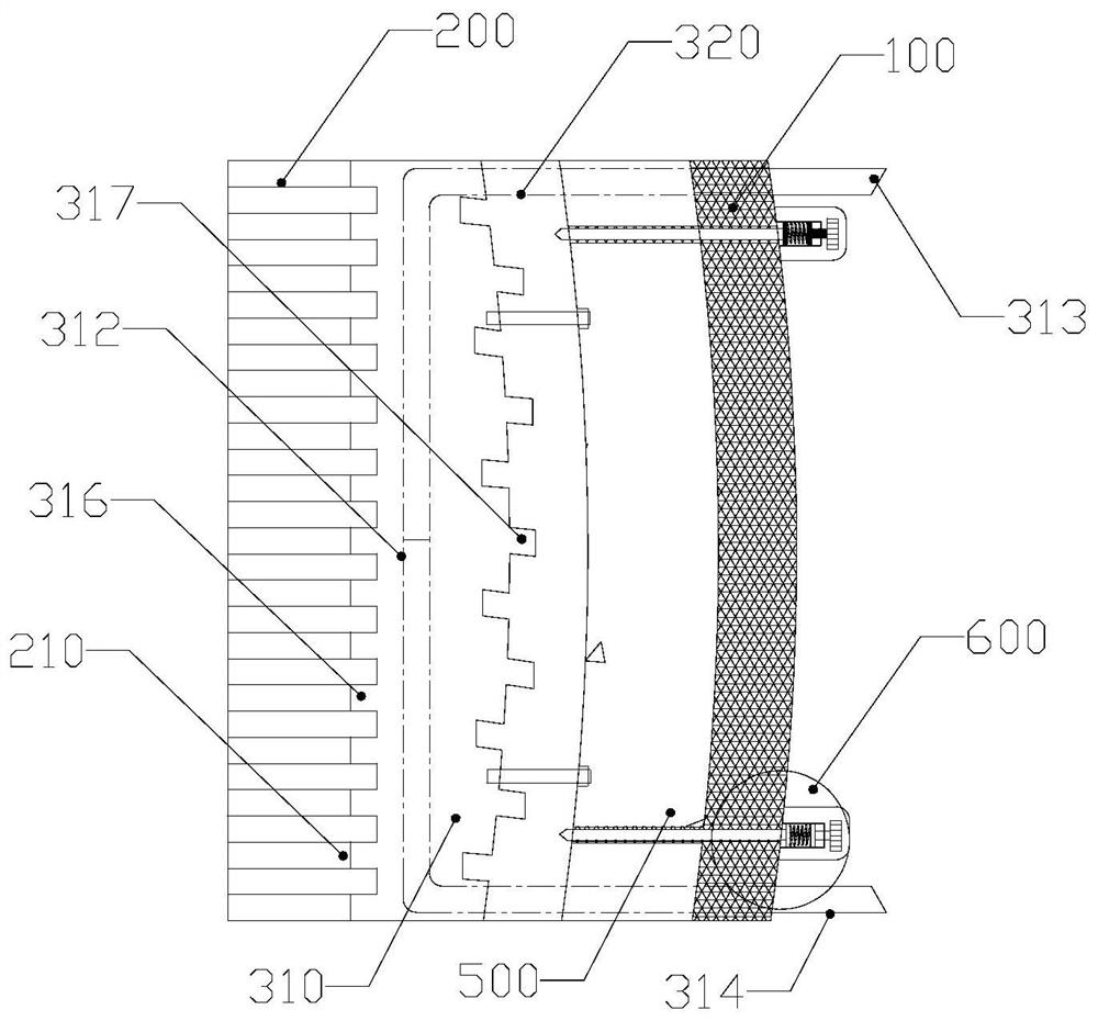
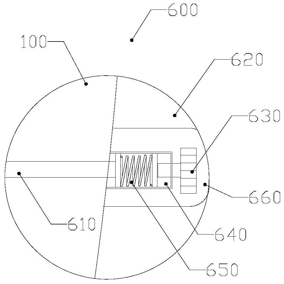
[0005] In order to solve the above-mentioned problems in the prior art, that is, in order to solve the problem that the refractory layer cannot be cooled in time, the present invention provides a cooling device for the transition zone of the smelting reduction furnace. The cooling device is arranged in a layered structure, including a hot surface cooling layer and a cold surface protection layer, the hot surface cooling layer is bonded to the refractory layer, the hot surface cooling layer includes a first metal shell and a cooling pipeline arranged inside the first metal shell, The cooling pipe passes through the first metal shell and extends to form a liquid inlet pipe and a liquid outlet pipe;

Method used


Image

  • Cooling device for transition area of smelting reduction furnace
  • Cooling device for transition area of smelting reduction furnace
  • Cooling device for transition area of smelting reduction furnace

Examples


Embodiment Construction

[0051] Those skilled in the art should understand that the embodiments described below are only preferred embodiments of the present invention, and the preferred embodiments are intended to explain the technical principles of the present invention, not to limit the protection scope of the present invention. Based on the embodiments provided by the present invention, all other embodiments obtained by persons of ordinary skill in the art without making creative efforts should still fall within the protection scope of the present invention.

[0052] It should be noted that, in the description of the present invention, the terms "center", "upper", "lower", "top", "bottom", "left", "right", "vertical", "horizontal", " Terms indicating directions or positional relationships such as "inner", "outer", etc. are based on the directions or positional relationships shown in the drawings, which are only for convenience of description, and do not indicate or imply that the device or element ...


PUM


Abstract

The invention provides a cooling device for a transition area of a smelting reduction furnace. The cooling device is set to be of a layered structure and comprises a hot surface cooling layer and a cold surface protection layer. The hot surface cooling layer is attached to a refractory layer, and comprises a first metal shell and a cooling pipeline arranged inside the first metal shell, wherein the cooling pipeline penetrates out of the first metal shell and extends to form a liquid inlet pipe and a liquid outlet pipe. The cold surface protection layer is attached to the hot surface cooling layer, and the cold surface protection layer and the refractory layer jointly clamp the hot surface cooling layer. The cold surface protection layer comprises a second metal shell, a liquid inlet through hole and a liquid outlet through hole, wherein the liquid inlet through hole and the liquid outlet through hole penetrate through the second metal shell, the liquid inlet pipe penetrates through the liquid inlet through hole, and the liquid outlet pipe penetrates through the liquid outlet through hole. The cooling device is arranged in the transition area of the smelting reduction furnace, and therefore the cooling device can reduce the surface temperature of the refractory layer, a stable slag iron solidification layer can be formed on the surface of the refractory layer in the transition area to protect the refractory layer, and the service life of the smelting reduction furnace is prolonged.

Description

technical field [0001] The invention belongs to the technical field of metallurgical equipment, and specifically provides a cooling device for a transition zone of a smelting reduction furnace. Background technique [0002] The HIsmelt smelting reduction process takes the smelting reduction furnace as the core, and produces high-quality pure iron by directly injecting iron ore powder and non-coking coal into the liquid iron molten pool in the smelting reduction furnace. Compared with the traditional blast furnace ironmaking process, the HIsmelt smelting reduction process has lower requirements for raw materials, and saves the two steps of sintering and coking. Under the same production capacity, the HIsmelt smelting reduction process can save a lot of investment and operating costs. [0003] However, the working conditions in the smelting reduction furnace are very harsh, especially in the transition zone where slag and iron coexist. The service life of the refractory layer...

Claims


Application Information

Patent Timeline
IPC IPC(8): F27D9/00C21B11/00
CPCF27D9/00C21B11/00F27D2009/0013F27M2003/13
Inventor 张冠琪陈庆孟王金霞张巧丽张晓峰
Owner SHANDONG MOLONG PETROLEUM MACHINERY
Learn More