Contact tip rotary lock of a welding torch

a technology of contact tip and welding torch, which is applied in the field of welding system, can solve the problems of reducing the maintenance complexity of welding system and the decrease of automatic complexity, and achieve the effect of simplifying the replacement and securement of components

Active Publication Date: 2017-03-23
ILLINOIS TOOL WORKS INC
View PDF98 Cites 26 Cited by
  • Summary
  • Abstract
  • Description
  • Claims
  • Application Information

AI Technical Summary

Benefits of technology

[0004]Therefore, it may be advantageous to provide a mechanism that simplifies replacement and securement of components within welding systems that are freque

Problems solved by technology

For example, automation complexity may decrease as maint

Method used


Image

  • Contact tip rotary lock of a welding torch
  • Contact tip rotary lock of a welding torch
  • Contact tip rotary lock of a welding torch

Examples


Embodiment Construction

[0039]One or more embodiments of the present disclosure will be described below. In an effort to provide a concise description of these embodiments, all features of an actual implementation may not be described in the specification. It should be appreciated that in the development of any such actual implementation, as in any engineering or design project, numerous implementation-specific decisions are made to achieve the developers' specific goals, such as compliance with system-related and business-related constraints, which may vary from one implementation to another. Moreover, it should be appreciated that such a development effort might be complex and time consuming, but would nevertheless be a routine undertaking of design, fabrication, and manufacture for those of ordinary skill having the benefit of this disclosure.

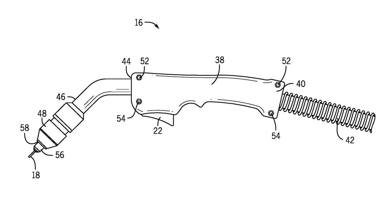
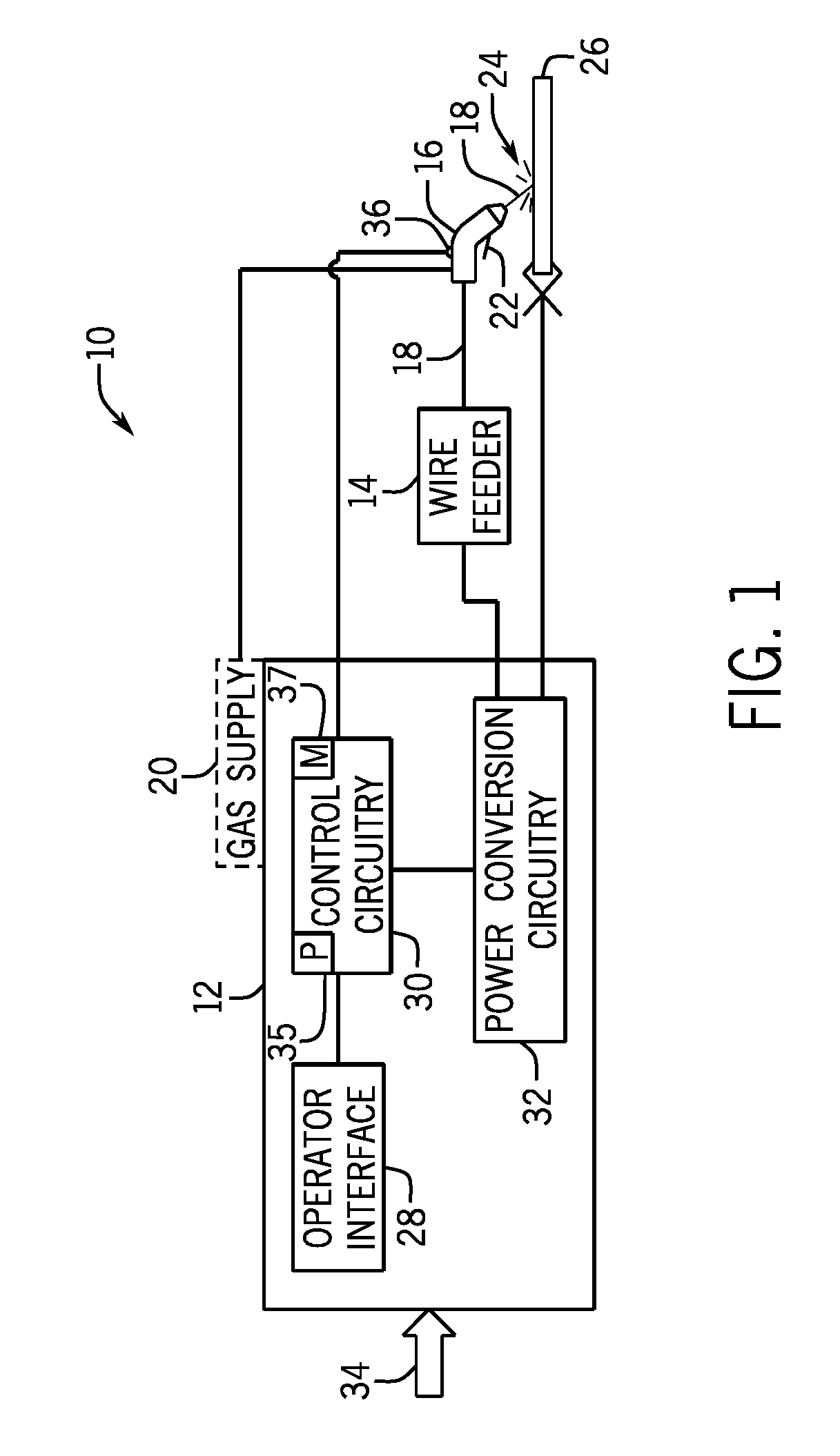
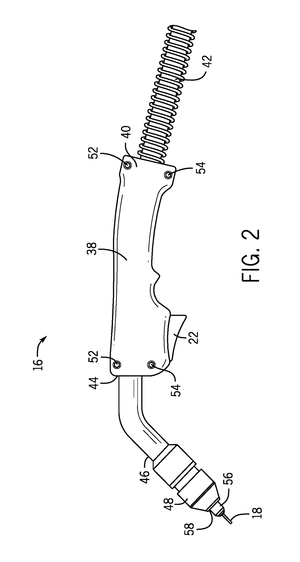
[0040]Turning now to the drawings, and referring first to FIG. 1, an exemplary welding system 10 is illustrated as including a power source 12 coupled to a wire fe...


PUM

PropertyMeasurementUnit
Angleaaaaaaaaaa
Forceaaaaaaaaaa
Electrical conductivityaaaaaaaaaa

Abstract

A welding torch system includes a diffuser assembly that includes a locking mechanism to receive a contact tip. Additionally, the welding torch system includes the contact tip, which includes locking elements configured to interact with the locking mechanism of the diffuser assembly to secure the contact tip within the diffuser assembly. Further, the contact tip is rotated within the diffuser assembly to securely align the locking elements with the locking mechanism.

Description

CROSS REFERENCE TO RELATED APPLICATION[0001]This application is a Non-provisional U.S. Patent Application of U.S. Provisional Application No. 62 / 220,671, entitled “Contact Tip Rotary Lock of a Welding Torch,” filed Sep. 18, 2015, which is hereby incorporated by reference in its entirety for all purposes.BACKGROUND[0002]The present disclosure relates generally to welding systems and, more particularly, to securement of contact tips in welding torches of welding systems.[0003]Welding is a process that has increasingly become ubiquitous in various industries and applications. Additionally, as welding has increased in general, automated welding processes are also becoming increasingly popular. With increasing automation in the field of welding, simple designs to meet automation maintenance goals are ever more valuable. For example, automation complexity may decrease as maintenance complexity of the welding systems also decreases.[0004]Therefore, it may be advantageous to provide a mecha...

Claims


Application Information

Patent Timeline
IPC IPC(8): B23K9/29B23P19/00
CPCB23P19/00B23K9/291B23K9/123B23K9/173
Inventor JAEGER, THOMAS ROGERWHIPPLE, BRADLEY EUGENE
Owner ILLINOIS TOOL WORKS INC
Why Eureka
Try Eureka