Turbo Machine

a technology of rotating wheels and rotating shafts, which is applied in the direction of liquid fuel engines, vessel construction, marine propulsion, etc., can solve the problems of high repair costs, increased wear, and certain tendency to oscillate, so as to improve aerodynamics and facilitate the removal of the shroud for maintenance or repair purposes

Inactive Publication Date: 2008-12-04
ALSTOM TECH LTD
View PDF5 Cites 6 Cited by
  • Summary
  • Abstract
  • Description
  • Claims
  • Application Information

AI Technical Summary

Benefits of technology

[0009]One of numerous aspects of the present invention includes providing, for at least one moving blade row, a shroud which connects all the moving blades of a moving blade row to one another at their tip in the circumferential direction and consequently, when the turbo machine is in operation, exerts no centrifugal forces on the moving blades, but, instead, deflects and absorbs the centrifugal forces in the circumferential direction. For this purpose, a shroud is provided which is formed from a plurality of separate shroud segments, which are assigned in each case to a plurality of moving blades, or from a plurality of separate shroud plates, which are assigned in each case to a moving blade, or from a single separate shroud ring which is assigned to all the moving blades of the respective moving blade row. At the same time, the shroud ring or the respective shroud segm...

Problems solved by technology

Furthermore, shrouds of this type lead to stabilization by virtue of the circumferential support of large blades or vanes which, because of their radial length, exhibit a certain tendency to oscillate when the turbo machine is in operation.
Insofar as the shrouds are also used as axial seals for individual blade rows, they may be exposed to increased wear, as a result of which repairs are required.
Insofar as the individual shroud plates or shroud portions, which, in the mounted state, in their entirety form the respective shroud, constitute an integral part...

Method used


Image

  • Turbo Machine
  • Turbo Machine
  • Turbo Machine

Examples


Embodiment Construction

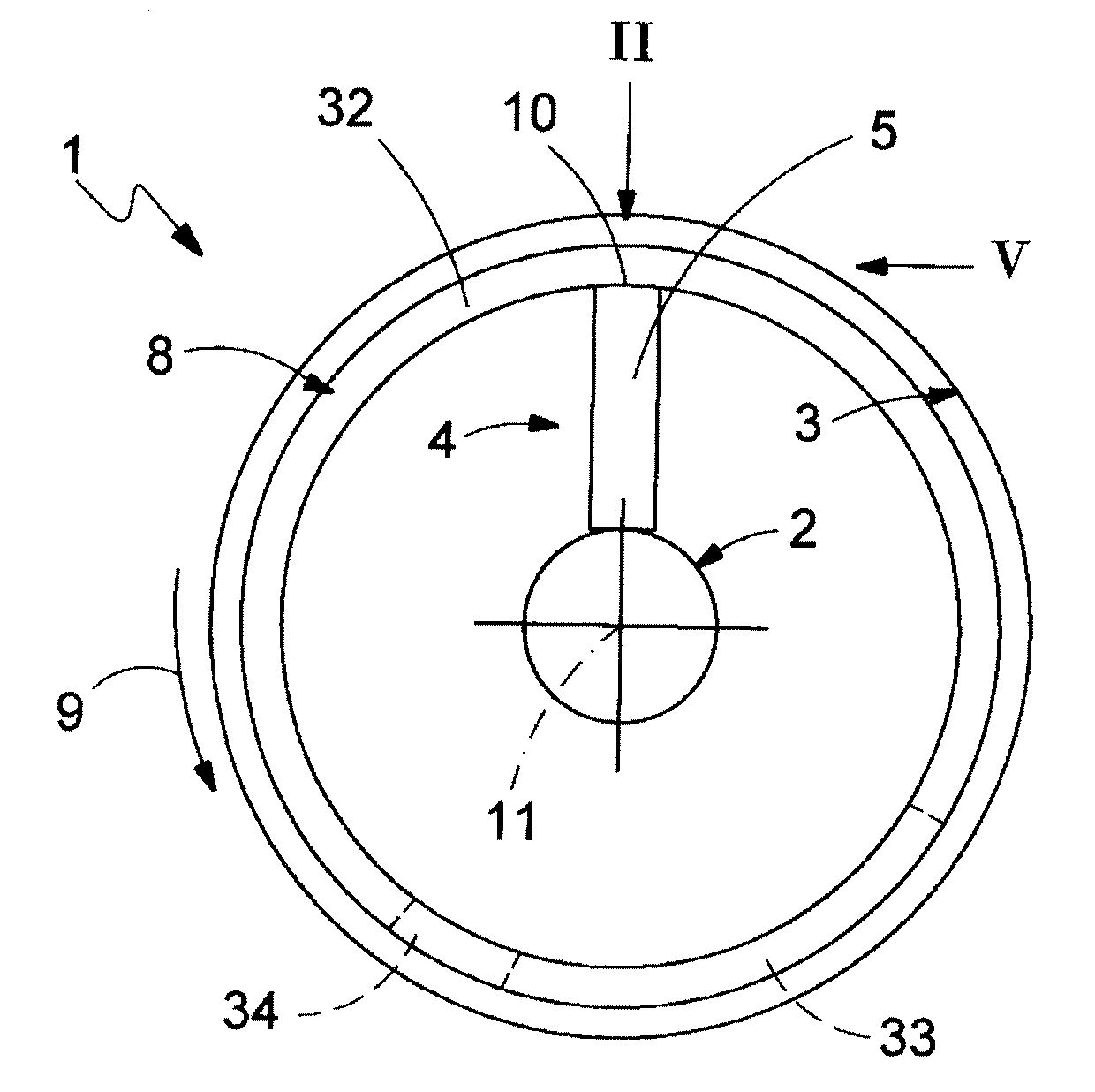
[0036]According to FIG. 1, a turbo machine 1 is equipped with a rotor 2 and with a stator 3. The rotor 2 is mounted rotatably in the stator 3 in the usual way. The turbo machine 1 may basically be a compressor or a turbine. Where a turbine is concerned, it may be a steam turbine or a gas turbine. The turbo machine 1 may be stationary and serve, for example, for driving a generator in a power plant. The turbo machine 1 may likewise be a drive assembly in a vehicle, in particular in an aircraft. However, an implementation of the invention in a configuration of the turbo machine 1 as a stationary gas turbine is preferred.

[0037]The rotor 2 has, according to FIG. 1, at least one moving blade row 4 which include a plurality of moving blades 5. The cross section according to FIG. 1 lies in the region of such a moving blade row 4, although only a single moving blade 5 is illustrated for the sake of clarity.

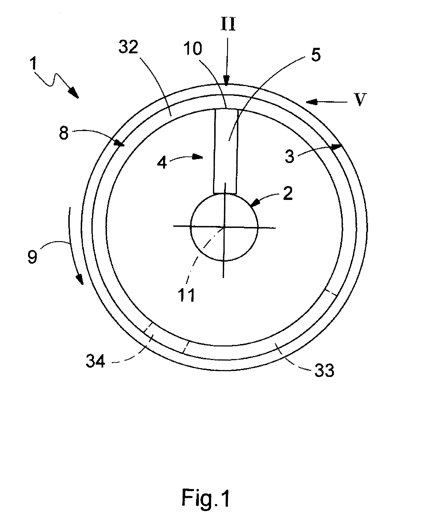
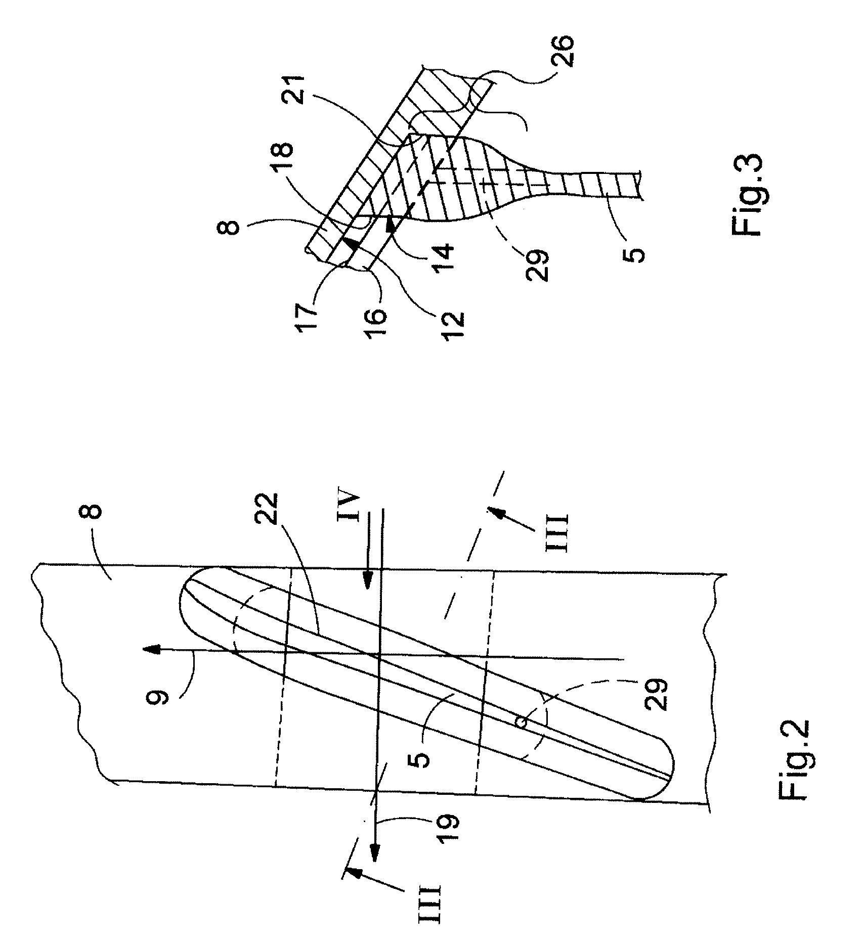
[0038]Moreover, the turbo machine 1 is equipped at least with a shroud 8. This shroud...


PUM


Abstract

A turbo machine (1, 101), in particular turbine or compressor, includes a rotor (2, 102) which has at least one moving blade row (4, 104) with a plurality of moving blades (5, 105), and a stator (3) which has at least one guide vane row (6, 106) with a plurality of guide vanes (7, 107), at least one moving blade row (4, 104) having a shroud (8, 108). The shroud (8, 108) is designed to be self-supporting in such a way that it can at least partially absorb the centrifugal forces arising during operation and discharge them in the circumferential direction.

Description

[0001]This application is a Continuation of, and claims priority under 35 U.S.C. § 120 to, International application no. PCT / EP2006 / 065879, filed 31 Aug. 2006, and claims priority therethrough under 35 U.S.C. §§ 119, 365 to Swiss application nos. 01508 / 05, 01509 / 05, both filed 15 Sep. 2005, the entireties of which are incorporated by reference herein.BACKGROUND[0002]1. Field of Endeavor[0003]The present invention relates to a turbo machine, in particular a turbine or a compressor, and, moreover, relates to a shroud or shroud ring for a turbo machine.[0004]2. Brief Description of the Related Art[0005]Turbo machines, such as turbines, in particular gas turbines and steam turbines, and also compressors, include a rotor which is mounted rotatably in a fixed stator. Turbo machines of this type are also designated as rotating turbo machines. The rotor in this case regularly includes a plurality of moving blade rows which in each case include a plurality of moving blades. Correspondingly, ...

Claims


Application Information

Patent Timeline
IPC IPC(8): F01D5/22
CPCF01D5/225F05B2240/33Y02T50/671Y02T50/673F05D2230/60F05D2260/30Y02T50/60
Inventor FERBER, JOERGENRITCHIE, JAMESSLOWIK, SLAWOMIR
Owner ALSTOM TECH LTD
Why Eureka
Try Eureka