Timing transmission having enhanced timing chain removal and replacement feature, and method

a technology of timing transmission and feature, which is applied in the direction of valve drives, machines/engines, gearing, etc., can solve the problems of chain used in timing transmission needing to be replaced (or repaired), difficult to gain access to the movable guide, and difficulty in resetting. to achieve the effect of simplifying the removal and replacement of timing chains

Inactive Publication Date: 2006-10-26
TSUBAKIMOTO CHAIN CO
View PDF7 Cites 8 Cited by
  • Summary
  • Abstract
  • Description
  • Claims
  • Application Information

AI Technical Summary

Benefits of technology

[0010] The timing transmission is incorporated in an internal combustion engine in an enclosed compartment formed by cooperation of a timing transmission cover with the engine block. Fastening means for attaching the timing transmission cover to the engine block, are loosenable to allow the timing transmission cover to be separated from the engine block sufficiently to provide access the transmission medium, and preferably also to the guide, through a space between the engine block and the edge of the timing transmission cover. The timing transmission cover has a through hole positioned so that a fixing jig extending through the hole can engage the engagement surface of the guide when the guide is moved to a tension-releasing position in which the transmission medium is allowed to be removed from the sprockets. The fixing jig holds the guide in the tension-releasing position, and the transmission medium can be removed from the sprockets while the timing transmission cover is separated from the engine block by only a short distance, without the need for insertion of a tool between the edge of the cover and the engine block to hold the movable guide in the tension-releasing position.
[0011] The length of the fastening means is preferably sufficient to allow the timing transmission cover to be separated from the engine block to allow access to the movable guide and the transmission medium through a space between the edge of the cover and the engine block without the fastening means being disconnected from the engine block. Preferably, the fastening means includes at least two fasteners that, when loosened, allow the timing transmission cover to be separated from the engine block sufficiently to allow access to the guide and the transmission medium through a space between the engine block and the edge of the timing transmission cover, while substantially preventing lateral movement of the timing transmission cover, that is, movement in directions parallel to the plane of movement of the traveling transmission medium. The through hole in the timing transmission cover is preferably sufficiently long and narrow to hold the fixing jig in a fixed position when the fixing jig is engaged with the engagement surface of the movable guide, and the movable guide is in the tension-releasing position.
[0012] The invention allows a timing transmission medium to be removed by a novel method, in which the fastening means which connect the timing transmission cover to the engine block are loosened sufficiently to provide access, through a space between the engine block and an edge of the cover, to the chain and preferably also to the movable guide, but not enough to allow the timing chain cover to shift parallel to the plane of travel of the chain. The movable guide is pushed in a direction to allow slack in the chain, preferably by gaining access to the movable guide through the space between the engine block and the edge of the cover. Then a fixing jig is inserted through a hole in the timing transmission cover, and engaged with the movable guide while the guide is positioned to allow slack in the chain. The fixing jig, in cooperation with the cover, temporarily prevents movement of the guide toward the chain, while the chain is removed from the sprockets.
[0013] The invention greatly simplifies the removal and replacement of a timing chain or the like, since it enables the chain to be removed and replaced without complete removal of the timing chain cover, while the engine remains in place in the engine compartment of the vehicle. The use of a fixing jig, in cooperation with the timing chain cover, to hold the movable guide in a tension-releasing condition, makes it possible for a single individual to remove a timing chain. The fixing jig holds the guide in the tension-releasing condition until the chain can be replaced. Consequently, the plunger is prevented from dropping out of the tensioner housing, and the steps of reassembling the tensioner, and pushing the lever to its tension-releasing position during installation of a replacement chain, are avoided.

Problems solved by technology

Frequently, the chain used the timing transmission needs to be replaced (or repaired) because of wear or excessive elongation.
Resetting is difficult to accomplish, especially in the case of a ratchet-type tensioner, since it is not easy to gain access to the ratchet mechanism of the tensioner in order to release the pawl or pawls, and push the plunger back into the housing.
In fact, in many cases, it is difficult to gain access to the movable guide.

Method used


Image

  • Timing transmission having enhanced timing chain removal and replacement feature, and method
  • Timing transmission having enhanced timing chain removal and replacement feature, and method
  • Timing transmission having enhanced timing chain removal and replacement feature, and method

Examples


Embodiment Construction

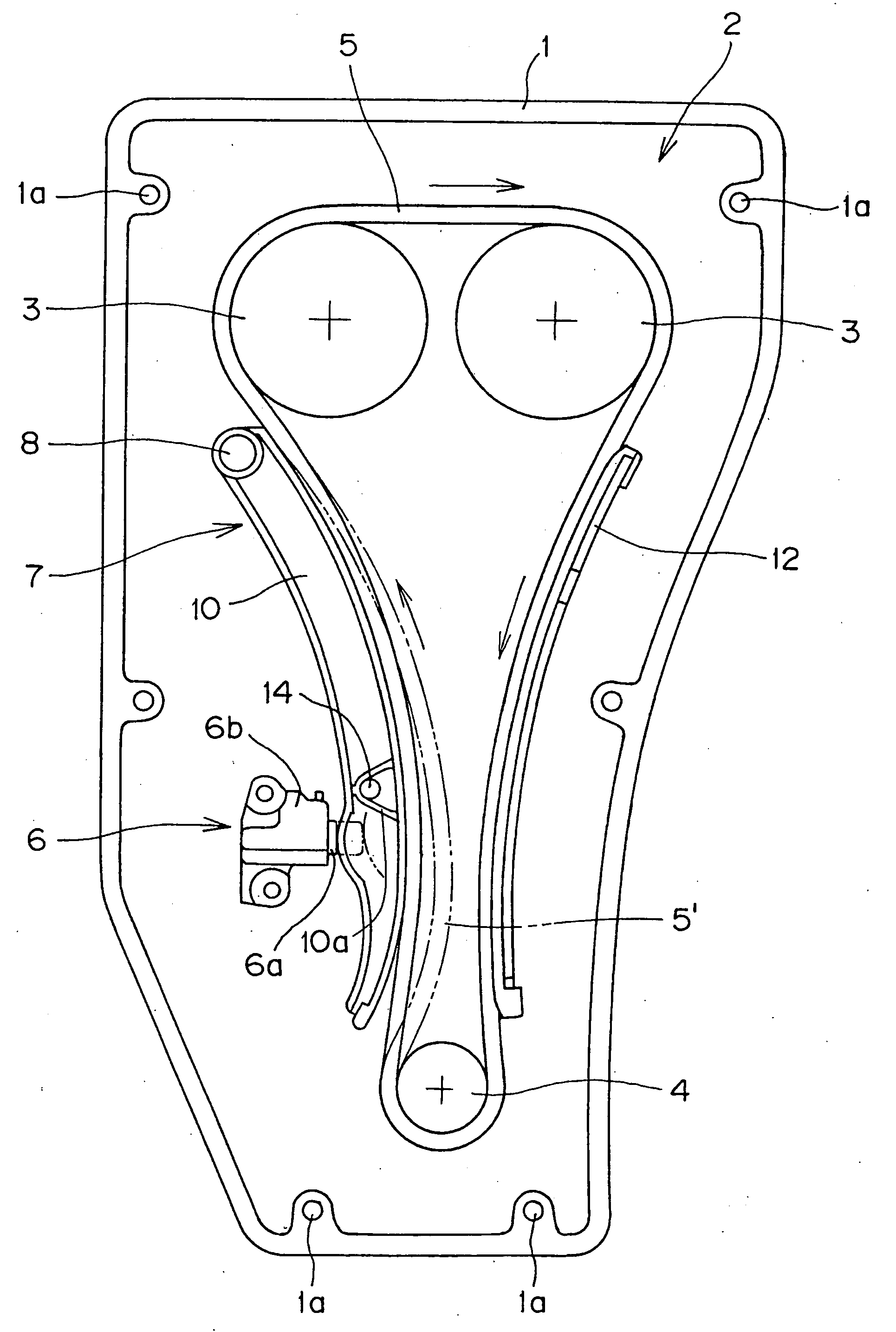
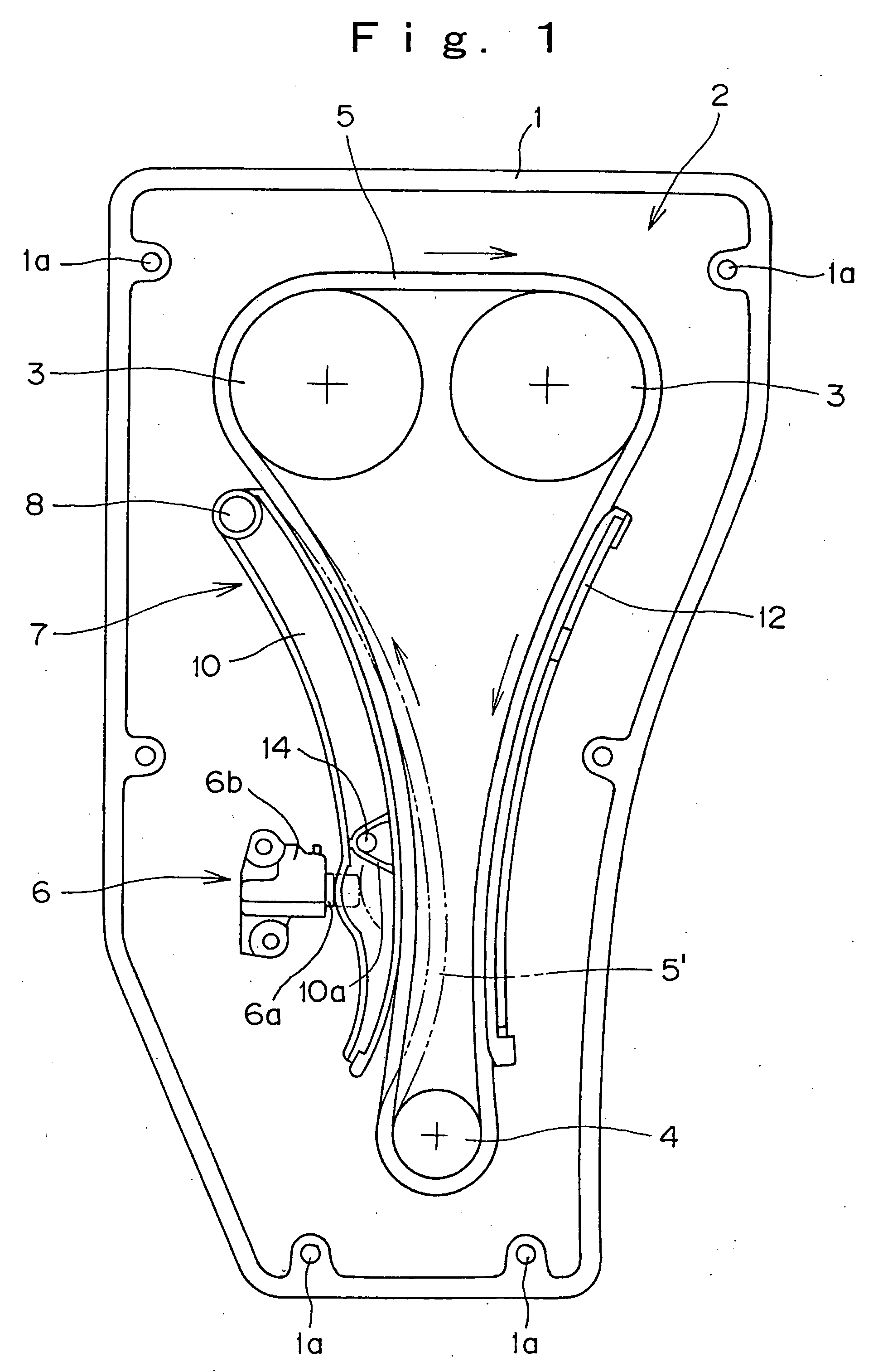
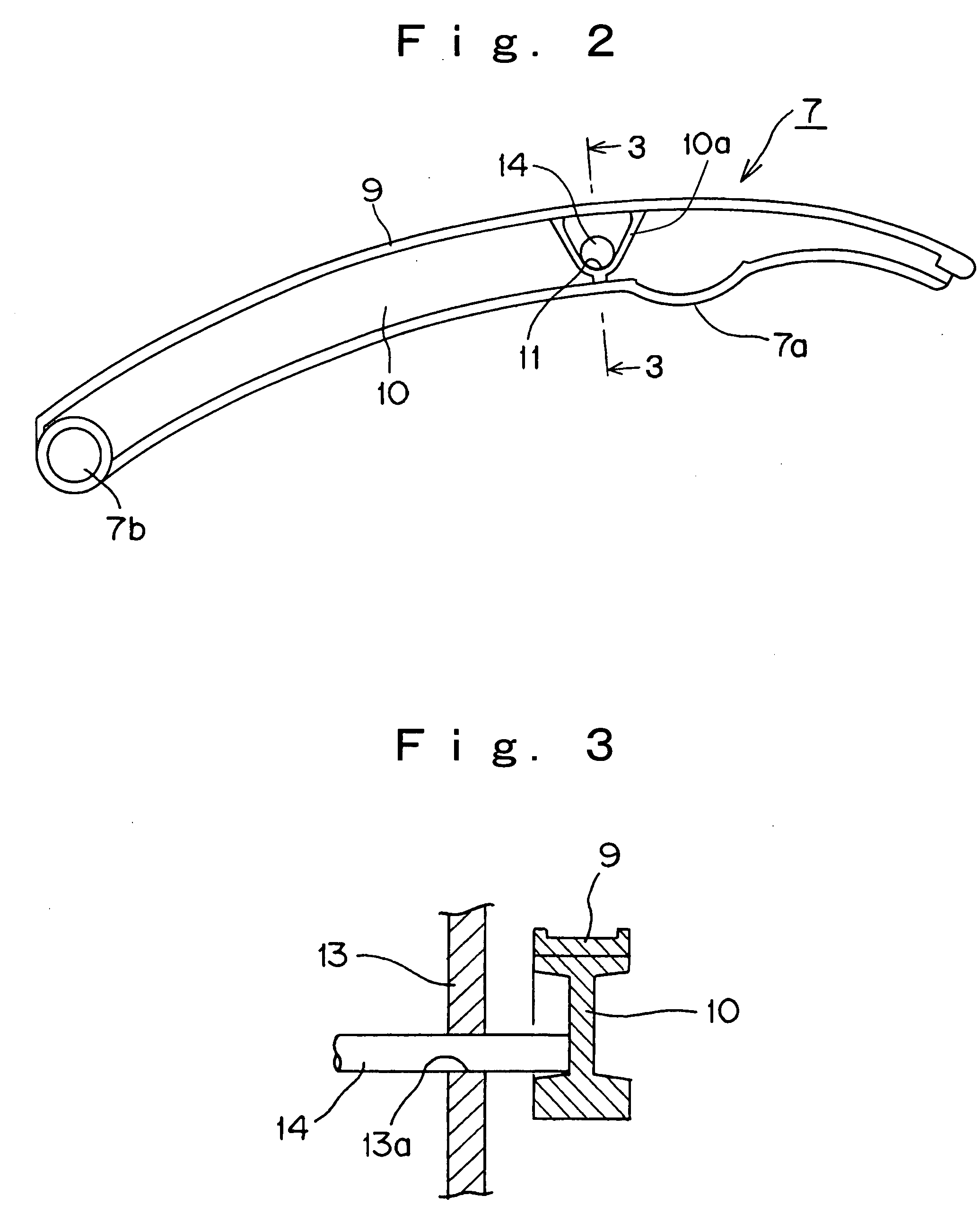
[0019] The conventional timing transmission, as shown in FIG. 5, is disposed within a timing transmission case 21 formed as an integral part of the engine block, and enclosed by a timing transmission cover (not shown). A chain 25 is in mesh with a crankshaft sprocket 24 and two camshaft sprockets 23. A fixed guide 31 is in sliding engagement with the tension side of the chain, i.e., the portion of the chain that moves from one of the camshaft sprockets 23 toward the crankshaft sprocket 24. A movable guide 27 is in sliding engagement with the slack side of the chain, i.e., the portion of the chain that moves from the crankshaft sprocket 24 toward one of the camshaft sprockets 23. The movable guide is pivoted on a shaft 28, which is fixed to the engine block, and is urged toward the chain by the plunger 26a of a tensioner 26, the plunger protruding from a tensioner housing 26b. The guide is composed of a chain-engaging shoe 29 mounted on a supporting member 30, having reinforcing ribs...


PUM


Abstract

In an internal combustion engine having a timing transmission, tension in the timing chain is released for removal of the chain by pushing a tensioner-urged movable guide away from the chain and holding the guide in a tension-releasing position by a fixing jig inserted through a hole in the timing chain cover while the timing chain cover is still connected to the engine block by partially loosened fasteners.

Description

CROSS-REFERENCE TO RELATED APPLICATIONS [0001] This application claims priority on the basis of Japanese patent application 2005-109787, filed Apr. 6, 2005. The disclosure of Japanese application 2005-109787 is hereby incorporated by reference. FIELD OF THE INVENTION [0002] The invention relates to improvements in the maintainability of the timing transmission of an internal combustion engine for a vehicle, and more particularly to a timing transmission having an enhanced timing chain removal and replacement feature, and to an improved method for timing chain removal and replacement. BACKGROUND OF THE INVENTION [0003] In the timing drive of most vehicular internal combustion engines, an endless, flexible, traveling, transmission medium is used to transmit power from crankshaft sprocket to one or more camshaft sprockets. The transmission medium is typically a roller chain, silent chain, toothed belt, or the like. [0004] For convenience, the invention will be described with reference ...

Claims


Application Information

Patent Timeline
Patent Type & Authority Applications(United States)
IPC IPC(8): F16H7/08F16H7/18
CPCF01L1/02F01L1/024F16H2007/0842F01L2103/01F01L1/053F01L2303/01
Inventor YOKOYAMA, MASANORI
Owner TSUBAKIMOTO CHAIN CO
Why Eureka
Try Eureka