Method and system for securing a cross member to a tube

a cross member and cross-section technology, applied in the direction of rod connections, curtain suspension devices, manufacturing tools, etc., can solve the problems of weakening against lateral or sheer forces, rotational forces and moment forces, and unable to secure the cross-section, so as to achieve the effect of convenient attachmen

Active Publication Date: 2015-02-10
SALTO LLC
View PDF18 Cites 8 Cited by
  • Summary
  • Abstract
  • Description
  • Claims
  • Application Information

AI Technical Summary

Benefits of technology

[0004]In view of the deficiencies and drawbacks in the prior art, it is a primary object of the present invention to provide a method and system for securing a cross member to a tube that provides increased attachment strength, especially against lateral, sheer, rotational forces and moment forces.
[0005]Another object of the present invention is to provide a method and system for securing a cross member to a tube, so that the point of attachment does not deform when force is applied to it.
[0006]A further object of the present invention is to provide a method and system for securing a cross member to a tube that is aesthetically pleasing and provides a clean look and feel.
[0007]An additional object of the present invention is to provide a method and system for securing a support to a tube that is simple to install and replace.
[0009]Once the upper body is attached to the tube, the lower body can easily be attached to the upper body to complete the cross member. The upper body includes a central projection and the lower body includes a receiving cavity, sized and shaped to receive the projection. The lower body further includes a screw hole and a screw. The screw is inserted through the screw hole and, when engaged, creates an interference fit between the screw, the central projection and an inner wall of the receiving cavity.

Problems solved by technology

Depending on the specific dimensions of the tube and the cross member, and depending on the amount of force that will be applied to the attachment, the attachment may fail if it is not strong enough.
Both the welding technique and fastener technique provide load and tension strength, but both are weak against lateral or sheer forces, rotational forces and moment forces.

Method used


Image

  • Method and system for securing a cross member to a tube
  • Method and system for securing a cross member to a tube
  • Method and system for securing a cross member to a tube

Examples


Embodiment Construction

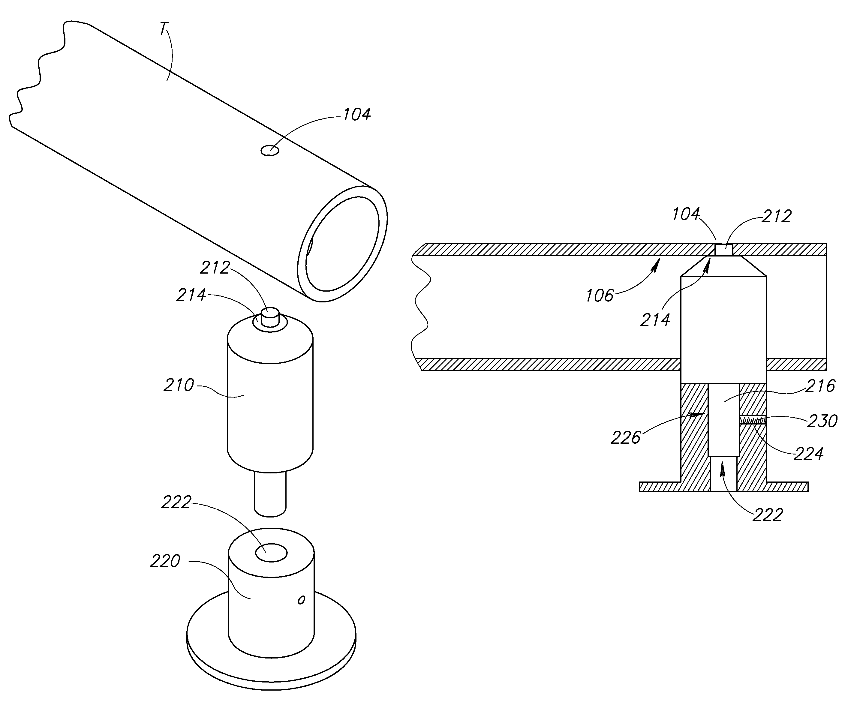
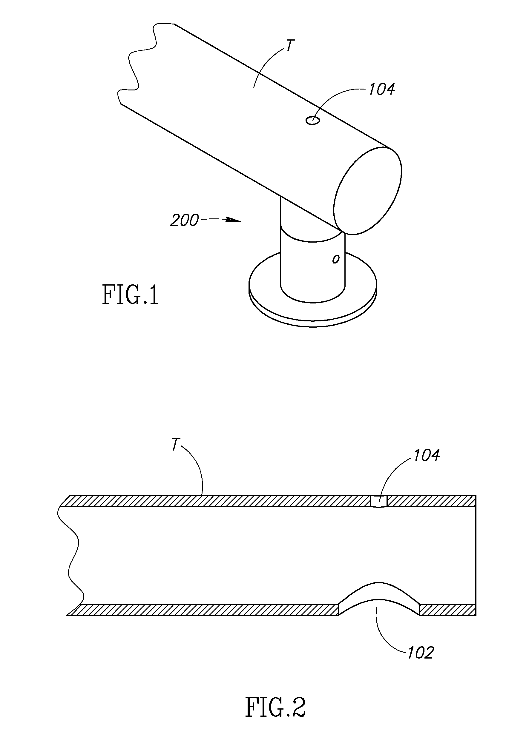
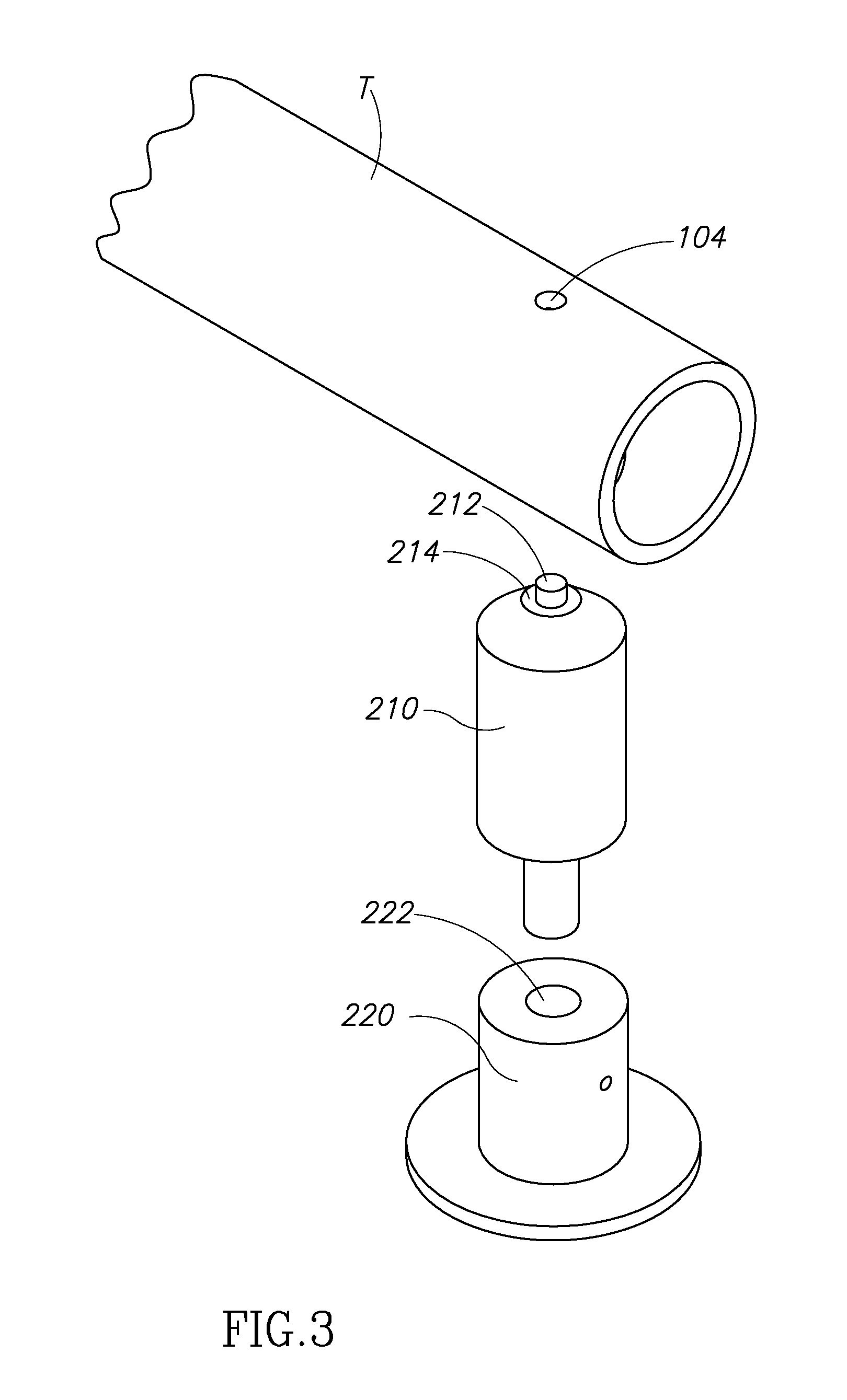
[0022]With reference to the accompanying drawings, there is shown in FIG. 1 a first preferred embodiment of a method and system of securing a cross member 200 to a tube T. Two holes, a first hole 102 and a second hole 104, are drilled in opposite surfaces of the length of the tube T. The first hole 102 is larger than the second hole 104. The cross member 200 further includes an upper body 210 and a lower body 220. In the first preferred embodiment of the present invention, all of the elements are constructed of metal.

[0023]FIG. 2 shows a cross-section of the tube T with the first hole 102 and the second hole 104 drilled at opposite surfaces. In the preferred embodiment, the tube T is a cylindrical tube, preferably stainless steel, though the invention is applicable to tubes of varying shape. See e.g., FIG. 8. The holes are formed using known drilling or punching techniques.

[0024]As illustrated in FIG. 3, the preferred embodiment of the complete system / method includes the assembly of...


PUM

PropertyMeasurementUnit
junction areaaaaaaaaaaa
areaaaaaaaaaaa
diameteraaaaaaaaaa

Abstract

There is provided in a preferred embodiment a method and system for attaching a cross member to a tube. The tube has two holes drilled into it at opposite surfaces. The upper body of the cross member is inserted into one hole, through the tube and into the opposite hole. At the opposite hole, the cross member is welded or otherwise affixed to the tube. The lower body of the cross member is designed and adapted to be selectively attached to the upper body.

Description

FIELD OF THE INVENTION[0001]This invention relates generally to a method and system for securing a cross member to a tube, bar or channel. The invention involves a stronger and more secure connection between the tube and the cross member. More specifically, this invention involves inserting the cross member through the diameter of a tube and securing the cross member to the opposite end from which it is inserted of the tube to create a stronger and more secure attachment.BACKGROUND OF THE INVENTION[0002]When securing a tube to a cross member, the strength and durability of the attachment may be important. Depending on the specific dimensions of the tube and the cross member, and depending on the amount of force that will be applied to the attachment, the attachment may fail if it is not strong enough.[0003]Existing attachment techniques include welding or fastening the cross member to the exterior of the tube / bar / channel. When fastening, a hole is drilled in the exterior of the tube...

Claims


Application Information

Patent Timeline
Patent Type & Authority Patents(United States)
IPC IPC(8): F16B9/02F16B7/04
CPCF16B7/0493F16B9/026F16B7/18F16B2200/406Y10T29/49826Y10T29/49963Y10T403/46
Inventor SISTO, SALVATORE J.
Owner SALTO LLC
Why Eureka
Try Eureka