Single lever turboprop control systems and methods utilizing torque-based and power-based scheduling

Active Publication Date: 2017-03-23
HONEYWELL INT INC
View PDF8 Cites 17 Cited by
  • Summary
  • Abstract
  • Description
  • Claims
  • Application Information

AI Technical Summary

Benefits of technology

[0003]Embodiments of a single lever turboprop control method are provided, which utilize torque-based and/or power-based scheduling to achieve a desired (e.g., substantially proportional) relationship between control lever position and the power output of a turboprop engine. In one embodiment, the method includes the step or process of monitoring, at an Engine Control Unit (ECU), for receipt of a Power Lever Angle (PLA) signal from a single lever control device. When a PLA control signal received at the ECU, a target torque or power output is established as a function of at least the PLA control signal. A first engine setpoint, such as a blade angle setpoint or an engine rotational speed setpoint, is selectively determined utilizing the target torque output. An operational parameter of the turboprop engine, such as engine rotational speed and/or propeller blade angle, is then adjusted in accordance with the first engine setpoint.
[0004]In a further embodiment, the single lever turboprop control method includes monitoring, at an ECU, for receipt of a PLA control signal from a single lever control device. When a PLA control signal is received at the ECU, a target power output for the turboprop engine is established as

Problems solved by technology

In further contrast to single lever turbofan and turbojet control systems, dual lever turboprop control systems typically do not provide pilot controls for adjusting the thrust or power output of the turboprop engine in a direct manner.
Such disparities in the control systems of tur

Method used


Image

  • Single lever turboprop control systems and methods utilizing torque-based and power-based scheduling
  • Single lever turboprop control systems and methods utilizing torque-based and power-based scheduling
  • Single lever turboprop control systems and methods utilizing torque-based and power-based scheduling

Examples


Embodiment Construction

[0010]The following Detailed Description is merely exemplary in nature and is not intended to limit the invention or the application and uses of the invention. Furthermore, there is no intention to be bound by any theory presented in the preceding Background or the following Detailed Description.

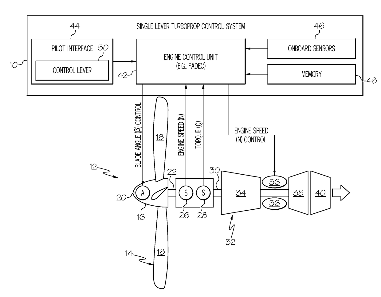
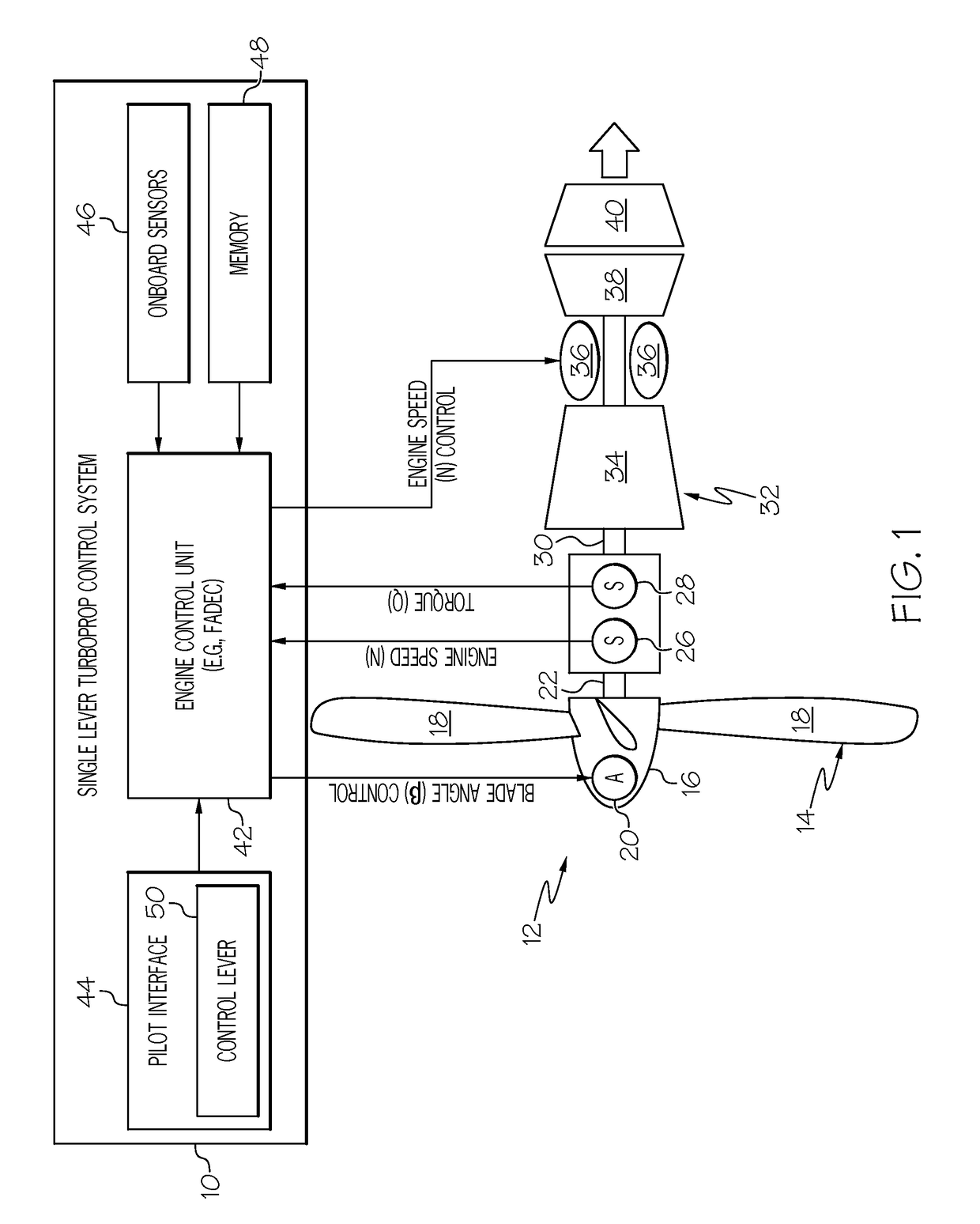
[0011]As briefly described above, turboprop engines are traditionally operated utilizing a dual lever control system, which includes a first lever for adjusting propeller blade angle (β) and a second, independent lever for adjusting engine rotational speed (N). Recently, certain turboprop control systems have been proposed that enable a pilot to adjust both propeller blade angle (β) and engine rotational speed (N) utilizing a single control lever located in the aircraft cockpit. During operation, such a single lever turboprop control system may convert or “schedule” the angular position of the control lever to a corresponding propeller blade angle setpoint (βset) and a corresponding rotation...


PUM


Abstract

Embodiments of a single lever turboprop control method and system are provided, which utilize torque-based and/or power-based scheduling to achieve a desired (e.g., substantially proportional) relationship between control lever position and the power output of a turboprop engine. In one embodiment, the method includes the step or process of monitoring, at an Engine Control Unit (ECU), for receipt of a Power Lever Angle (PLA) signal from a single lever control device. When a PLA control signal received at the ECU, a target torque or power output is established as a function of at least the PLA control signal. A first engine setpoint, such as a blade angle setpoint or an engine rotational speed setpoint, is determined utilizing the target torque output. An operational parameter of the turboprop engine is then adjusted in accordance with the first engine setpoint.

Description

TECHNICAL FIELD[0001]The following disclosure relates generally to gas turbine engines and, more particularly, to single lever turboprop control systems and methods utilizing torque-based and / or power-based scheduling to achieve a desired (e.g., substantially proportional) relationship between control lever position and the power output of a turboprop engine.BACKGROUND[0002]Fixed wing aircraft are commonly equipped with one of three types of propulsive gas turbine engines: turboprop, turbofan, or turbojet engines. Turbofan and turbojet engines are typically operated utilizing a single lever control system, which includes a cockpit lever movable through a range of angular positions to schedule engine thrust. Turboprop engines, by comparison, are typically operated utilizing a dual lever control system, which includes a first cockpit lever for controlling propeller blade angle and a second cockpit lever for controlling engine rotational speed. Thus, relative to single lever turbofan a...

Claims


Application Information

Patent Timeline
IPC IPC(8): B64D31/06B64C11/40B64D27/10B64C11/34
CPCB64D31/06B64D27/10B64C11/40B64C11/34B64D31/04B64D31/14B60W2710/0666
Inventor LOOPER, DAVECOFFEY, SCOTXIONG, YUFEI
Owner HONEYWELL INT INC
Why Eureka
Try Eureka