Spring probe and probe card having spring probe

Active Publication Date: 2017-03-23
MICROELECTRONICS TECH INC
View PDF2 Cites 8 Cited by
  • Summary
  • Abstract
  • Description
  • Claims
  • Application Information

AI Technical Summary

Benefits of technology

[0010]The present invention has been accomplished in view of the above-noted circumstances. It is an objective of the present invention to provide a spring probe and a probe card having the spring probe, wherein the spring probe can be i

Problems solved by technology

This phenomenon may result in problems of inaccurate alignment, unstable probing pressure, and the tendency of fracture of the probe.
If the probe is fractured, more problems will arise, such as difficulties in maintaining and replacing the probe.
Further, because the installing hole 174 has a large radius, which makes the adjacent probes quite distanced from each other, the fine pitch requirement of the high-density probe card can hardly be fulfilled.
Furthermore, when the circuit board 15 is not yet disposed on the top surface 175 of the p

Method used


Image

  • Spring probe and probe card having spring probe
  • Spring probe and probe card having spring probe
  • Spring probe and probe card having spring probe

Examples


Example

[0026]First of all, it is to be mentioned that same reference numerals used in the following preferred embodiments and the appendix drawings designate same or similar elements throughout the specification for the purpose of concise illustration of the present invention.

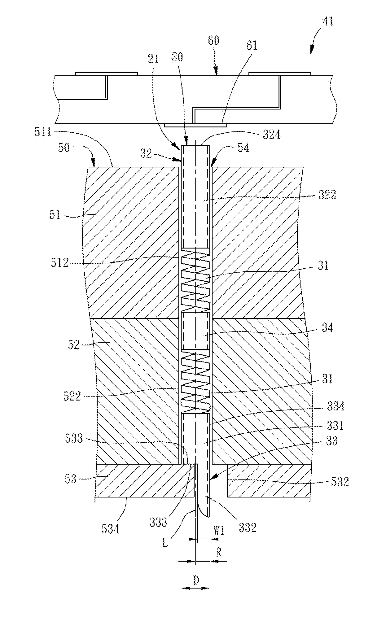
[0027]Referring to FIG. 4, a spring probe 21 according to a first preferred embodiment of the present invention includes a spring sleeve 30. A circular metal pipe with uniform diameter is processed by photolithography technique to form at least one spring section 31 helically opened through an outer circumferential surface thereof, thereby becoming the spring sleeve 30. The at least one spring section 31 is located between an upper non-spring section 32 and a lower non-spring section 33. Besides, the lower non-spring section 33 is formed from an originally complete cylinder as the upper non-spring section 32. A part of the originally complete cylinder is removed by a process such as etching, so that the cylinder becom...


PUM


Abstract

A probe card includes a probe seat having upper and lower dies and a probe accommodating hole, a spring probe inserted through the probe accommodating hole and including a spring sleeve having upper and lower non-spring sections, and a circuit board disposed on the upper die and having a contact pad against which the spring probe is abutted. At least one of the upper and lower dies has a stopping surface partially facing the probe accommodating hole and an extended portion inserting hole in alignment with the probe accommodating hole. At least one of the upper and lower non-spring sections has a cylinder portion abutted on the stopping surface and an extended portion inserted through the extended portion inserting hole.

Description

BACKGROUND OF THE INVENTION[0001]1. Field of the Invention[0002]The present invention relates generally to spring probes and more particularly, to a sleeve-type spring probe and a probe card having the spring probe.[0003]2. Description of the Related Art[0004]FIG. 1 is an exploded plan view of a conventional spring probe 11 which includes a needle 12, and a spring sleeve 13 sleeved onto the needle 12. FIG. 2 is a schematic sectional view of a probe card 14 using the spring probe 11. For the convenience of illustration, FIG. 2 is not drawn to the same scale with FIG. 1. The probe card 14 includes a circuit board 15 and a probe device 16. The circuit board 15 may be the circuit board adapted for being electrically connected with a tester (not shown). Alternately, the circuit board 15 may be a space transformer disposed between the probe device 16 and the circuit board (not shown) adapted for being electrically connected with a tester (not shown). The probe device 16 includes a probe s...

Claims


Application Information

Patent Timeline
IPC IPC(8): G01R1/067G01R31/28H01R12/71
CPCG01R1/06722G01R31/2808H01R12/71
Inventor CHEN, TSUNG-YIKUO, TING-HSINLEE, YI-LUNGCHEN, SHIH-SHINSUN, HORNG-CHUANFAN, HORNG-KUANG
Owner MICROELECTRONICS TECH INC
Why Eureka
Try Eureka