Touch panel with antenna structure

a technology of antenna structure and touch panel, which is applied in the field of touch panel, can solve the problems of easy generation of signal interference problems, complicated installation process of conventional antennas, and inability to further reduce the thickness of electronic devices, so as to improve the performance of the antenna radiation unit to receive and transmit wireless signals and improve the touch control performance of the touch panel

Inactive Publication Date: 2017-03-23
J TOUCH CORPORATION
View PDF8 Cites 16 Cited by
  • Summary
  • Abstract
  • Description
  • Claims
  • Application Information

AI Technical Summary

Benefits of technology

[0005]An object of the present invention provides a touch panel with an antenna structure. The touch panel is applied to an electronic device with a wireless communication function. Since the grounding part is disposed on the periphery wiring zone of the transparent substrate to isolate signals, the grounding part can be used as a ground terminal of the antenna radiation unit in order to avoid the signal interference problem. Under this circumstance, the touch control performance of the touch panel will be increased, and the performance of the antenna radiation unit to receive and transmit the wireless signals will be enhanced.

Problems solved by technology

In other words, the thickness of the electronic device cannot be further reduced.
Moreover, the process of installing the conventional antenna is complicated and costly, and the signal interference problem is readily generated.
Under this circumstance, the performance of the antenna to receive and transmit the wireless signals and the touch sensing performance of the touch panel are adversely affected.

Method used


Image

  • Touch panel with antenna structure
  • Touch panel with antenna structure
  • Touch panel with antenna structure

Examples


Embodiment Construction

[0019]The present invention will now be described more specifically with reference to the following embodiments. It is to be noted that the following descriptions of preferred embodiments of this invention are presented herein for purpose of illustration and description only. It is not intended to be exhaustive or to be limited to the precise form disclosed.

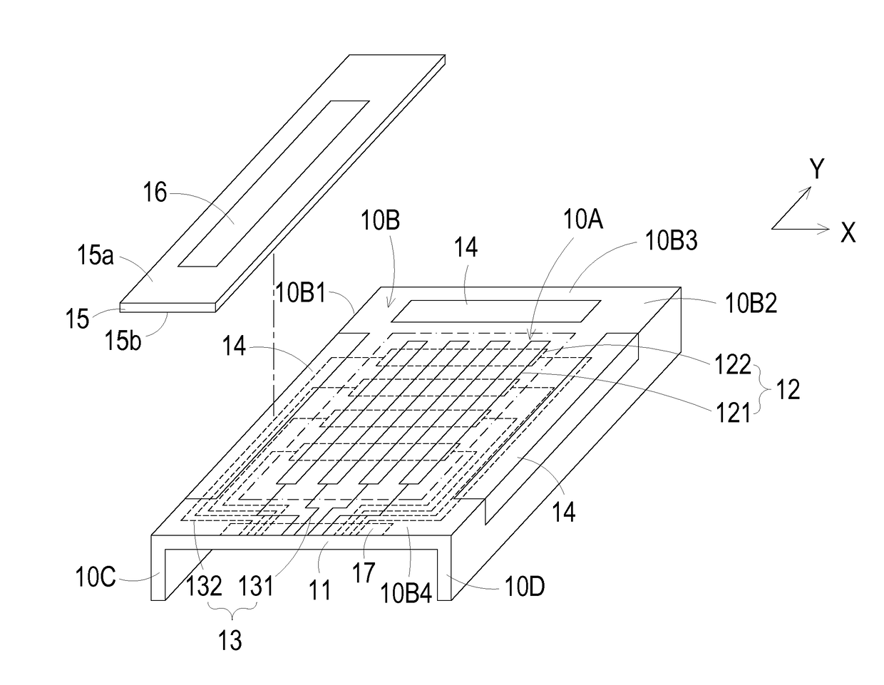
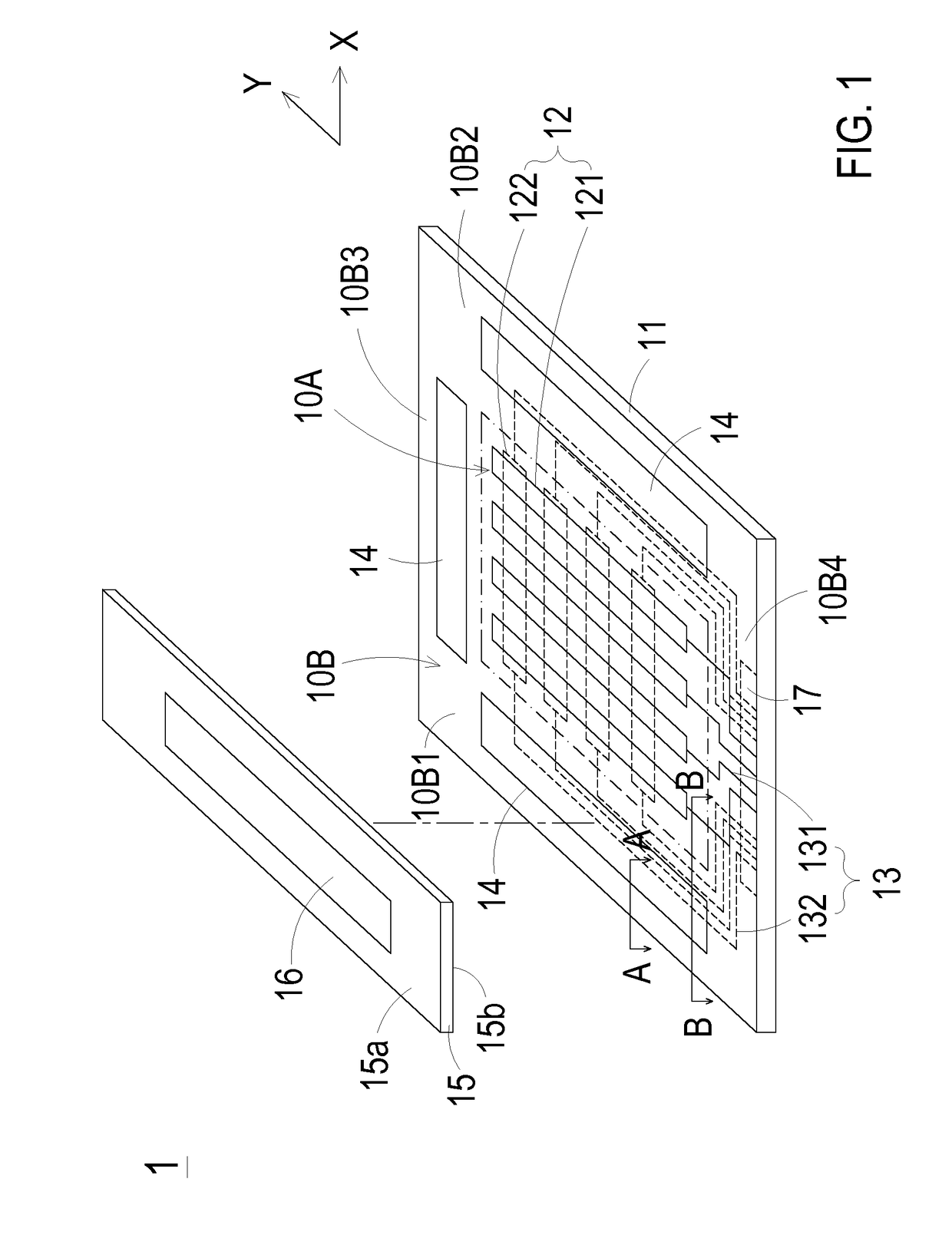
[0020]FIG. 1 schematically illustrates a touch panel with an antenna structure according to an embodiment of the present invention. The touch panel 1 of the present invention can be applied to an electronic device with a wireless communication function. The touch panel 1 can provide a touch control function and a function of receiving and transmitting wireless signals. An example of the electronic device includes but is not limited to a mobile phone, a tablet computer, a portable computer or a wearable electronic device. In this embodiment, the touch panel 1 comprises a transparent substrate 11, a touch sensing circuit 12, plural...


PUM


Abstract

A touch panel with an antenna structure is provided. The touch panel includes a transparent substrate, a touch sensing circuit, plural metal traces, a grounding part, an insulation film, and an antenna radiation unit. The transparent substrate is divided into a visible touch zone and a periphery wiring zone around the visible touch zone. The touch sensing circuit is included in the visible touch zone. The plural metal traces are included in the periphery wiring zone. The grounding part is included in the periphery wiring zone. A bottom surface of the insulation film is connected with the periphery wiring zone of the transparent substrate. The antenna radiation unit is disposed on a top surface of the insulation film. At least a portion of the antenna radiation unit is disposed over the grounding part, and electrically connected with the grounding part.

Description

FIELD OF THE INVENTION[0001]The present invention relates to a touch panel, and more particularly to a touch panel with an antenna structure.BACKGROUND OF THE INVENTION[0002]Nowadays, touch control technologies are widely applied to the touch display devices of various electronic devices in order to facilitate the users to control the operations of the electronic devices. Conventionally, a touch panel comprises a substrate, plural sensing electrodes and plural metal traces. The substrate is divided into a visible touch zone and a periphery wiring zone. The plural sensing electrodes are disposed on the substrate and located at the visible touch zone. The plural metal traces are disposed on the substrate, and located at the periphery wiring zone. The plural metal traces are electrically connected with the corresponding sensing electrodes.[0003]With increasing development of information and communication technologies, the electronic devices with wireless communication functions become ...

Claims


Application Information

Patent Timeline
Patent Type & Authority Applications(United States)
IPC IPC(8): G06F3/041
CPCG06F3/0418G06F2203/04103G06F3/0412G06F3/041G06F2203/04102G06F2203/04107
Inventor YEH, YU-CHOUYEN, YU-HONGLIN, TING-CHINGTSUI, CHIU-CHENGCHUANG, CHIA-SO
Owner J TOUCH CORPORATION
Why Eureka
Try Eureka