Intelligent 3D fixture design method

a design method and intelligent technology, applied in the field of intelligent 3d fixture design method, can solve the problems of difficult optimization, difficult to determine the effect of cad software during the design stage, and difficult to determine the effect of cad software, etc., and achieve the effect of optimizing (and inexpensive) typ

Inactive Publication Date: 2008-02-28
NAT KAOHSIUNG UNIV OF SCI & TECH
View PDF0 Cites 6 Cited by
  • Summary
  • Abstract
  • Description
  • Claims
  • Application Information

AI Technical Summary

Benefits of technology

[0010]A primary objective of the present invention is to provide an intelligent 3D fixture design method, which can solve interference problems between each workpiece, tool and fixture module, and which optimizes types, specifications and layouts of fixture modules over large numbers of design parameters. As shown in FIG. 9, the present invention can check interference between fixture modules, movement interference between workpieces and fixture modules, and / or interference between tools and fixture modules during operation, while satisfying fixing position and / or fixing force requirements of the fixture module, thereby obtaining an optimal (and inexpensive) type and related specification and layout of fixture system.

Problems solved by technology

Currently, fixture system designs utilize computer-aided design (CAD) software, which has parametric standard parts and / or fixture modules drawing files, however, this CAD software suffers from the following problems:It is not easy to determine during the design stage whether there will be interference between fixture modules, interference in the movement between a workpiece and a fixture module, or interference between a tool and a fixture module.The designing process may involve too many parameters related to select the type of fixture module and design its specification and layout, which are difficult to optimize.
However, the above-mentioned studies focus on fixture designs for machine tools, which are inadequate for dealing with complicated shapes workpieces, fixtures and tools, or simultaneously providing decisions for types, specifications and layouts of fixtures.
These involve in resolving a large numbers of parameters and include the inability to determine whether, and at what position, interference exists, extreme difficulty in obtaining optimal designs, long design times, and poor universality.

Method used


Image

  • Intelligent 3D fixture design method
  • Intelligent 3D fixture design method
  • Intelligent 3D fixture design method

Examples


Embodiment Construction

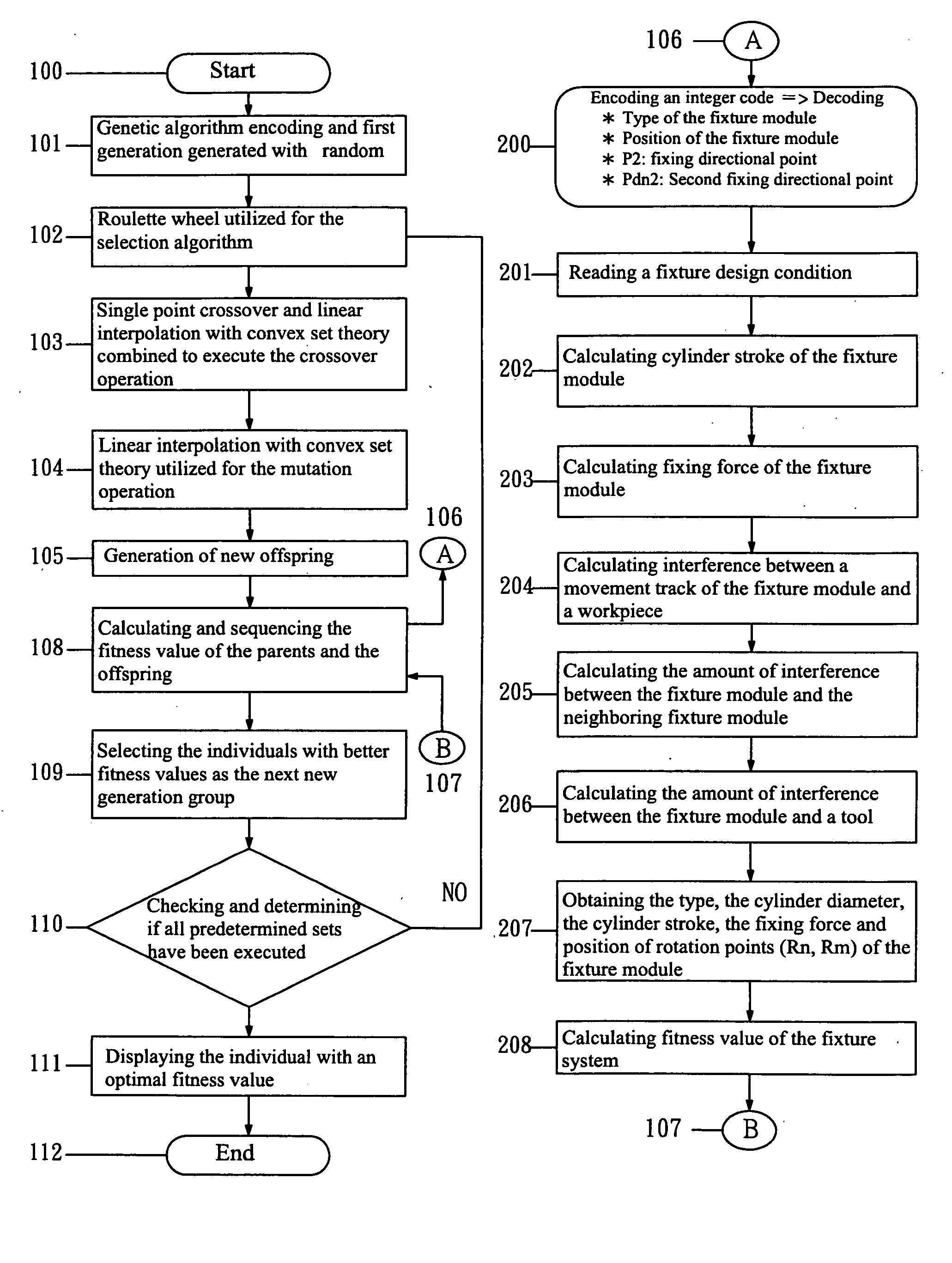
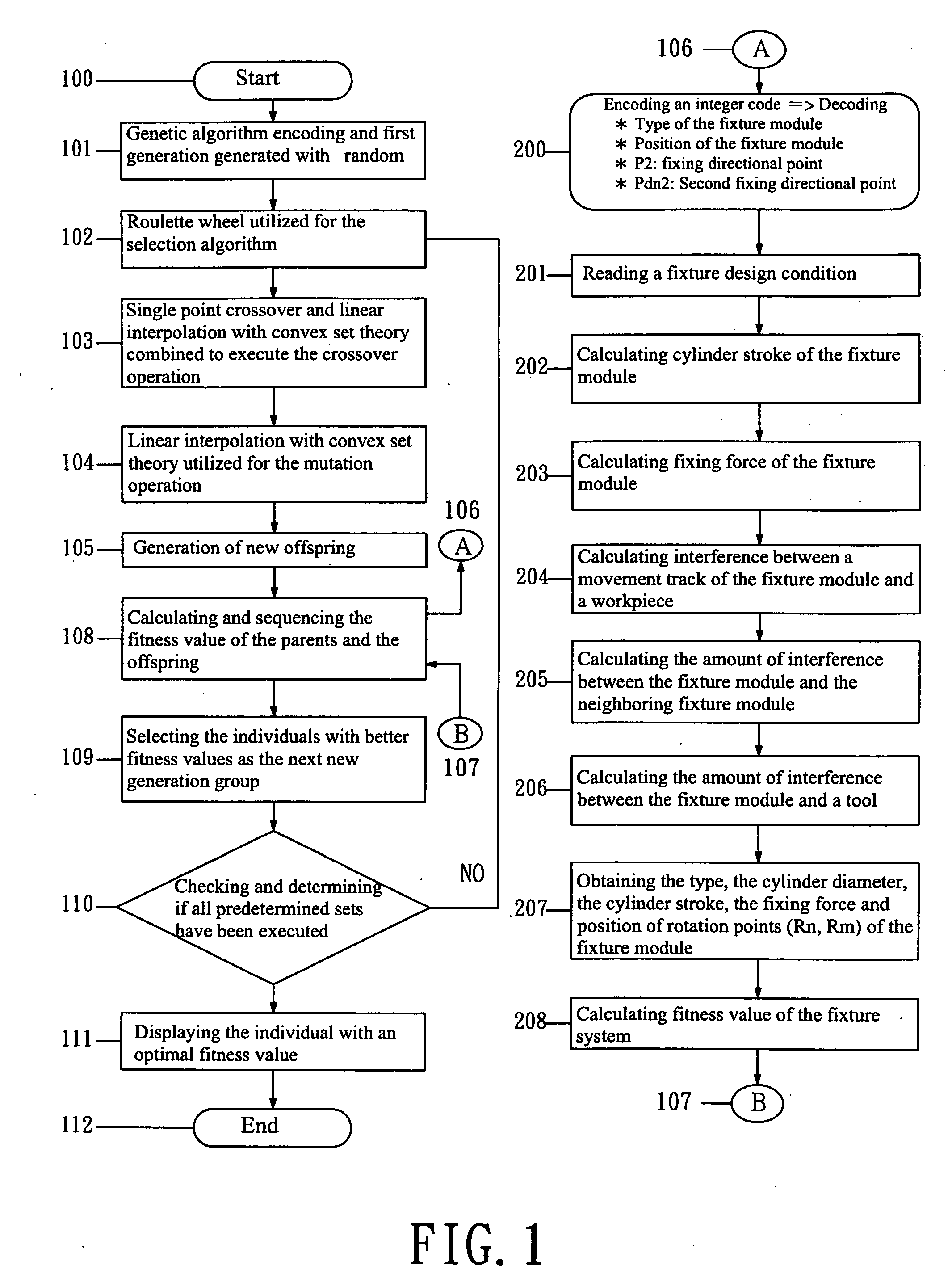
[0034]The intelligent 3D fixture design method of the present invention has a flow chart as shown in FIG. 1, which shows that, after a genetic coding operation, the first group is randomly generated; after a selection operation, a crossover operation, and a mutation operation, a new offspring is generated; after decoding the code and reading the associated fixture design conditions, a cylinder stroke of the fixture module is determined, as are a fixing force of the fixture module, movement tracking and workpiece interference amounts of the fixture module, interference amounts between the fixture module and its neighbor fixture module, and interference amounts between the fixture module and tools. The type, cylinder diameter, cylinder stroke, fixing force, and position of rotation points (Rn, Rm) of the fixture module are thereby obtained. Fitness values of the fixture system are determined; the fitness value order of the parent and the new offspring operated by the mutation operatio...


PUM


Abstract

An intelligent 3D fixture design method, which can solve interference problems between each workpiece, tool and fixture module to design optimal types, specifications and layouts of the fixture system. The design method of the present invention is based on a parametric solid model of 3D CAD software, which uses a space vector to determine if interference exists, and the interference position of such, between the solid models of workpieces, tools and fixture modules, and further utilizes a genetic algorithm to search type and its design shape and position parameters of each fixture modules, to design an optimal fixture system and related specification and layout.

Description

BACKGROUND OF THE INVENTION[0001]1. Field of the Invention[0002]The present invention relates to an Intelligent 3D Fixture Design method, which can be applied in industries that have fixture design optimization requirements, such as in: fixture system design industries, various mechanical process industries, various mechanical assembly industries, etc. The above-mentioned requirements include avoiding interference between fixture modules, avoiding movement interference between workpieces and fixture modules, and / or avoiding interference between tools and fixture modules during operation while satisfying fixing position and / or fixing force requirements, thereby obtaining an optimal (inexpensive) fixture system and related specification and layout. The intelligent 3D fixture design of the present invention solves these above-mentioned problems.[0003]2. Description of the Related Art[0004]With improvements in computer-related technologies, more and more industries rely on automated and...

Claims


Application Information

Patent Timeline
Patent Type & Authority Applications(United States)
IPC IPC(8): G06F19/00
CPCG06F17/5095G06F30/15
Inventor LIN, BOR-TSUENLIU, TUNG-KUANTSAI, CHIA-NUNG
Owner NAT KAOHSIUNG UNIV OF SCI & TECH
Why Eureka
Try Eureka