Lidar using negative correlation

Inactive Publication Date: 2020-02-27
KOREA ADVANCED INST OF SCI & TECH
View PDF0 Cites 6 Cited by
  • Summary
  • Abstract
  • Description
  • Claims
  • Application Information

AI Technical Summary

Benefits of technology

[0020]Further, according to the present invention having the above-described configuration, it is possible to provide a LIDAR capa

Problems solved by technology

Meanwhile, currently commercially available LIDAR systems have a problem that the LIDARs interfere with each other.
Therefore, when a plurality of LIDARs in operation are present within a measurement area, serious measurement errors may occur due to the interference between the LIDARs, and thereby causing an accident.
In addition, since measures against physical hacking are not provided in the conventional LIDARs, there is a possibility to be abused such as terrorism using hacking.
However, since the method of Non-Patent Document 1 does not use

Method used


Image

  • Lidar using negative correlation
  • Lidar using negative correlation
  • Lidar using negative correlation

Examples


embodiment 1

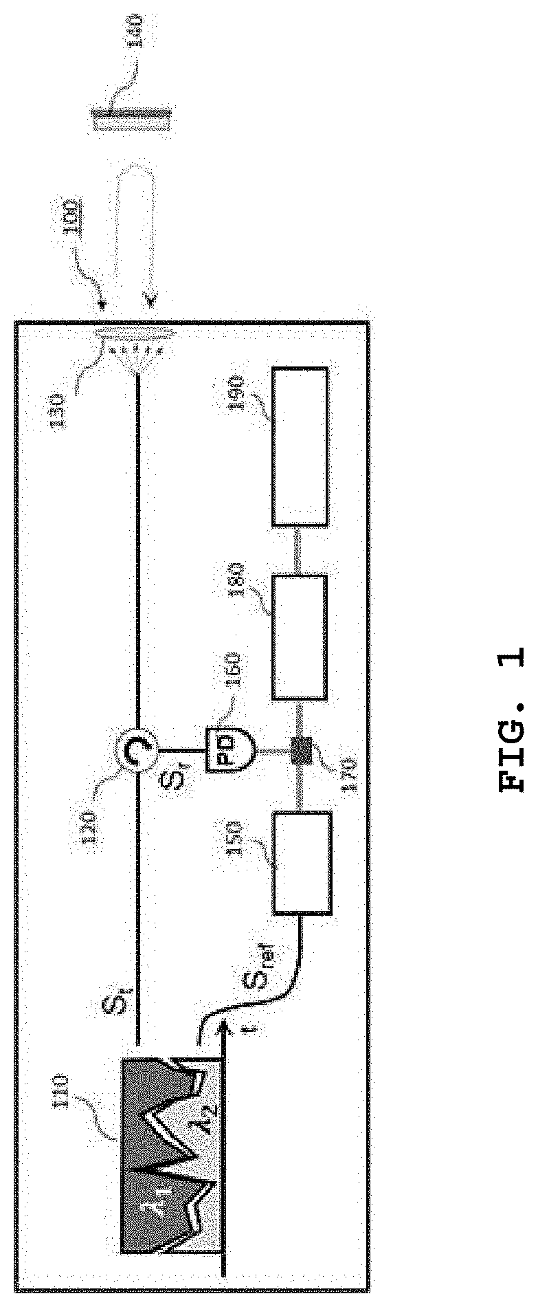
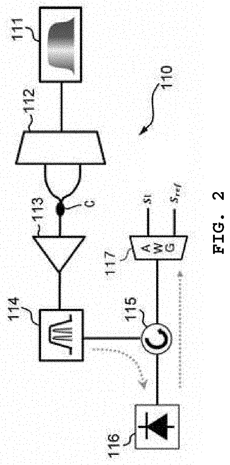
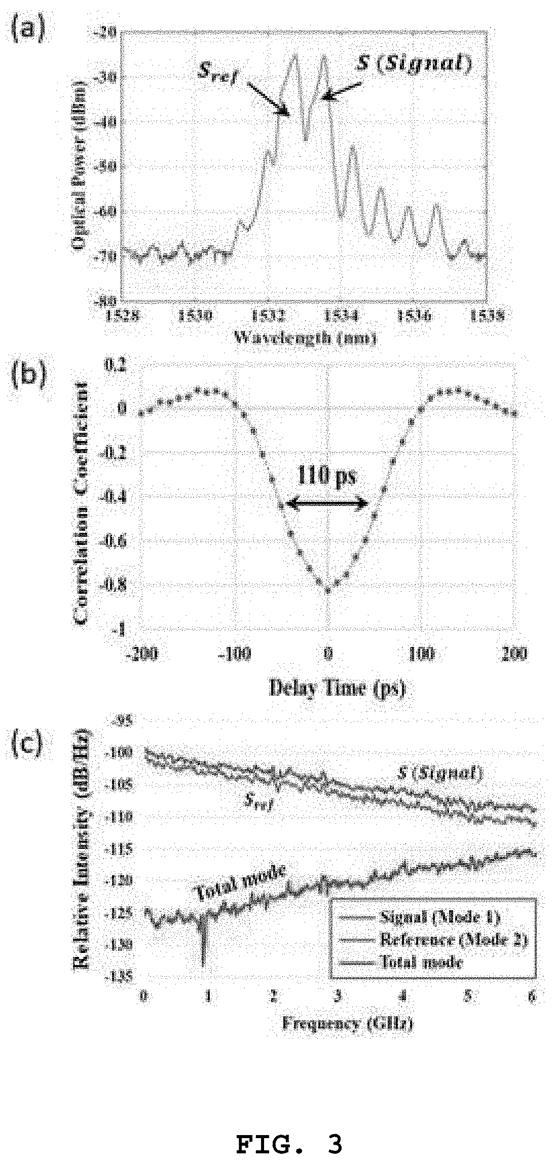
[0030]First, preferred Embodiment 1 of the present invention will be described with reference to FIGS. 1 to 6. FIG. 1 is a diagram illustrating a configuration of a LIDAR according to preferred Embodiment 1 of the present invention, FIG. 2 is a diagram illustrating a configuration of a correlation signal generation unit illustrated in FIG. 1, FIG. 3 is graphs illustrating characteristics of outputs from the correlation signal generation unit, FIG. 4 is a diagram illustrating an example for implementing a delay time adjustment unit illustrated in FIG. 1 as an electronic device, FIG. 5 is graphs illustrating a principle of implementing the delay time decision unit illustrated in FIG. 1, and FIG. 6 is a graph illustrating results of correlation restoration by the LIDAR of Embodiment 1.

[0031]As illustrated in FIG. 1, a LIDAR 100 according to preferred Embodiment 1 of the present invention includes a correlation signal generation unit 110 which generates a negative correlation (i.e., inv...

embodiment 2

[0078]Next, preferred Embodiment 2 of the present invention will be described with reference to FIG. 7.

[0079]A LIDAR 200 according to preferred Embodiment 2 of the present invention employs a detection method for improving the reception sensitivity of the LIDAR using a so-called coherent detection method. As described above, the coherent detection method is already known in the art.

[0080]Embodiment 2 of the present invention proposes a LIDAR capable of analyzing a change in the polarization of a received signal while improving the reception sensitivity using such a conventional coherent detection method, and capable of quickly detecting the cross-correlation.

[0081]FIG. 7 is a diagram illustrating a configuration of the LIDAR according to preferred Embodiment 2 of the present invention. As illustrated in FIG. 7, the LIDAR 200 of Embodiment 2 includes a correlation signal generation unit 210, a local oscillator LO, an optical circulator 220, a signal transmission / reception unit 230, t...

modified embodiment

[0100]While the present invention has been described with reference to preferred Embodiments 1 and 2, the present invention is not limited to the above-described embodiments, and various alterations or modifications may be possible without departing from the scope of the present invention.

[0101]In the above Embodiments 1 and 2, the configuration, in which the reference signal Sref of an optical signal is converted into an electric signal by the delay time adjustment unit 150 or the delay time adjustment unit 250, and the converted electric signal is delayed by an appropriate delay time, then the delayed electric signal is combined with the received signal Sr converted into an electric signal by the photodetector 160 or the four photodetectors 260a, 260b, 260c and 260d, has been described, but it is not limited thereto. First, it may be configured in such a way that the reference signal Sref of an optical signal is delayed for an appropriate delay time, and then combined with the rec...


PUM


Abstract

The present invention provides a LIDAR 100 including a correlation signal generation unit 110 for generating two or more different correlation signals, a signal transmission/reception unit 130 for outputting a part of the two or more correlation signals as a transmission signal St, and receive a signal returned by reflecting from a target 140 among the output transmission signals St as a received signal Sr, a delay time adjustment unit 150 for delaying a reference signal by an appropriate delay time using the reference signal Sref, and a delay time decision unit 180 for determining whether a signal obtained by adding the received signal and the delay reference signal together has an SNR higher than a threshold, thus to determine whether the delay time delayed by the delay time adjustment unit 150 is appropriate or not, and a processing unit 190 for confirming characteristics of the target 140.

Description

CROSS-REFERENCE TO RELATED APPLICATIONS[0001]This application claims priority to Korean Patent Application No. 10-2018-0097513, filed on Aug. 21, 2018 in the Korean Intellectual Property Office, the entire disclosure of which is incorporated herein by reference.BACKGROUND OF THE INVENTION1. Field of the Invention[0002]The present invention relates to a decorrelated LIDAR using negative correlation signals or signals having a negative correlation therebetween.2. Description of the Related Art[0003]Light detection and ranging (LIDAR) devices are configured to confirm characteristics (a distance between the LIDAR device and a target to be measured, a shape of the target, and a three-dimensional image of the target, etc.) of the measurement target from a time in which a laser beam emitted from a light source is returned by scattering or reflecting from the target, changes in the intensity, frequency, and polarization state thereof, and have higher measurement accuracy than the radars, c...

Claims


Application Information

Patent Timeline
IPC IPC(8): G01S17/93G01S7/487G01S17/931
CPCG01S2013/9315G01S7/4873G01S2007/4975G01S17/931G01S7/499G01S7/4913G05D1/024G02B5/30
Inventor LEE, CHANG-HEEHWANG, IL-PYEONGKYE, MYEONGGYUNJEONG, YONGJUNKIM, JONGWANLEE, KWANYONGYUN, SEOKJUN
Owner KOREA ADVANCED INST OF SCI & TECH
Why Eureka
Try Eureka