Self-error injection technique for point-to-point interconnect to increase test coverage

Inactive Publication Date: 2017-03-23
QUALCOMM INC
View PDF6 Cites 4 Cited by
  • Summary
  • Abstract
  • Description
  • Claims
  • Application Information

AI Technical Summary

Benefits of technology

[0006]This Summary is provided to introduce a selection of concepts in a simplified form that are further described below in the Detailed Description. This Summary is not intended to identify key features or essential features of the claimed subject matter.
[0007]One aspect of the disclosure describes a device for testing error handling, the device comprising: at least one error insertion circuit; an on-chip hardware error-generator component coupled, via the at least one error insertion circuit, to at least one data line between two sub-components in the device, the on-chip hardware error-generator component configured to: receive an error simulation input; determine a data error pattern based, at least in part, on the error simulation input; and insert the data error pattern, via the at least one error insertion circuit, on the at least one data line effective to generate an error condition.
[0008]One aspect of the disclosure describes a method for testing error handling, the method comprising: receiving, using a hardware error-generator component, an error simulation input; determining, using the hardware error-generator component, a data error pattern to insert on at least one digital data line coupled to the hardware error-generator component; and inserting, using the hardware error-generator component, the data error pattern on the at least one digital data line effective to generate

Problems solved by technology

However, in a real-world implementation, physical properties introduce error into the data lines, corrupting the data being transferred.
Since errors can manifest in a variety of ways, it can be chal

Method used


Image

  • Self-error injection technique for point-to-point interconnect to increase test coverage
  • Self-error injection technique for point-to-point interconnect to increase test coverage
  • Self-error injection technique for point-to-point interconnect to increase test coverage

Examples


example environment

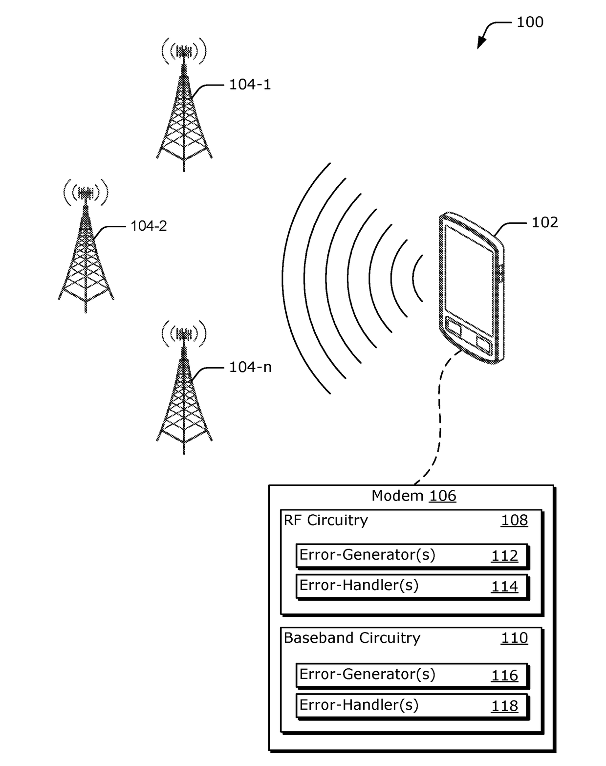
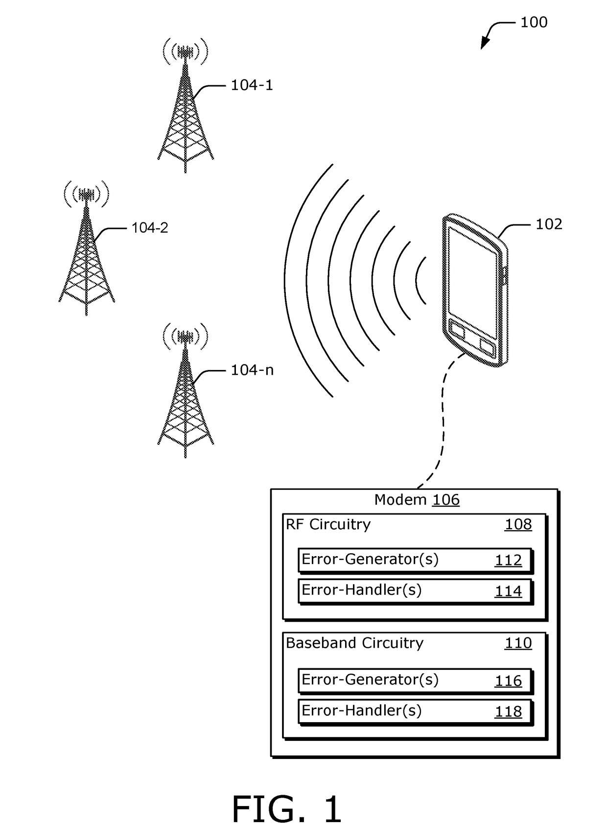
[0021]FIG. 1 illustrates example environment 100 comprising user device 102. Here, user device 102 is shown as a cellular mobile device, but any suitable type of computing device, such as a tablet, laptop computer, a set-top box, satellite receiver, cable television receiver, Wi-Fi access point, desktop computer, gaming device, display device, or the like can be used. In this example, user device 102 includes wireless communication capabilities, and is configured to communicate with any or all of cell towers 104-1 through 104-n, where “n” represents an arbitrary number. These cell towers work in conjunction to communicate with user device 102 and allow user device 102 to move from location to location without losing a communication link. Here, user device 102 includes modem 106 to perform at least part of these communications.

[0022]Modem 106 transmits and receives wireless signals and / or data. In some aspects, modem 106 is a circuit board that electrically connects various electroni...


PUM


Abstract

Various aspects describe an on-chip, hardware error-generator component. In some cases, the hardware error-generator component connects to a data path between two components contained within a same chip. Upon receiving an error simulation input, the hardware error-generator component modifies data being transmitted on the data path by inserting a data pattern that simulates an error condition. Alternately or additionally, the hardware error-generator randomly alters one or more of the transmitted data bits.

Description

RELATED APPLICATIONS[0001]This application claims priority to U.S. Provisional Patent Application No. 62 / 222,726, filed Sep. 23, 2015, the disclosure of which is incorporated by reference herein in its entirety.BACKGROUND[0002]Field of the Disclosure[0003]This disclosure relates generally to error-injection control and, more specifically, to on-chip error-generator components.[0004]Description of Related Art[0005]Computing devices today conventionally include multiple components that are interconnected with one another through data lines. Each component performs a respective functionality and interconnects with one another to request or share results. Thus, data lines are used by the components to communicate data or information back and forth to achieve an overall goal. Ideally, data lines successfully transmit and receive data without error. However, in a real-world implementation, physical properties introduce error into the data lines, corrupting the data being transferred. Sinc...

Claims


Application Information

Patent Timeline
IPC IPC(8): G06F11/26G06F11/27G06F11/263H04L69/40
CPCG06F11/261G06F11/27G06F11/263H04L1/241H04L2001/0093
Inventor CHENG, SCOTT WANG-YIPKHAN, RAHEELBANGA, KANWAL
Owner QUALCOMM INC
Why Eureka
Try Eureka