
Endosseous Dental Implant

a dental implant and endosseous technology, applied in dental implants, dental surgery, medical science, etc., can solve the problems of difficult insertion of implants, small thickness of patient's bone, and very small operation, and achieve efficient and simple insertion of implants, rapid and simple insertion, and great primary stability

Active Publication Date: 2017-03-30
REX IMPLANTS LLC
View PDF3 Cites 0 Cited by
  • Summary
  • Abstract
  • Description
  • Claims
  • Application Information

AI Technical Summary

Benefits of technology

The present invention is a dental implant that can be used in small-thickness zones of the bone crest, with limited volumetric dimensions and optimal anchoring in the bone. It has a surface area similar to standard-size implants and ensures an excellent primary stability. The implant has a central body with a conical or frustoconical shape and a blade positioned in a longitudinal mid-plane of the central body. It can be easily and precisely inserted in the patient's bone, with a predetermined insertion axis that maintains its stability and prevents transverse movements. This implant also has the function of expanding the bone during insertion and allows for the replacement of a single tooth. The technical effects of this invention are improved bone quality and reduced surgery time, leading to a reduction of risk factors and bone trauma.

Problems solved by technology

There are cases where the thickness of the patient's bone in which the implant is to be performed is very small, for example from 2.5 mm to 6 mm, and in such cases insertion of the implant is very difficult since, in order to be able to insert the implant, it is required to perform complicated regenerative surgery using special bone grafts.

Method used


Image

  • Endosseous Dental Implant
  • Endosseous Dental Implant
  • Endosseous Dental Implant

Examples


first embodiment

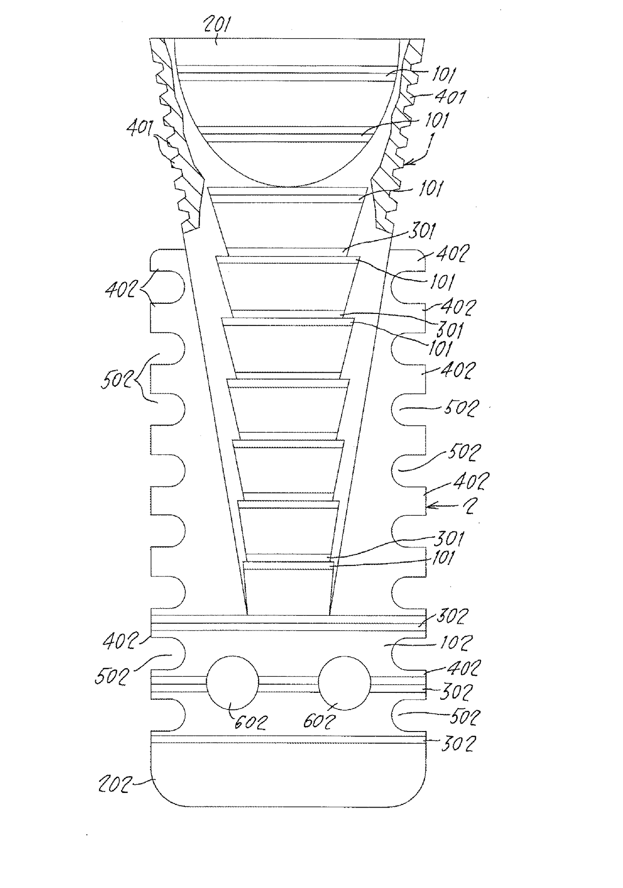
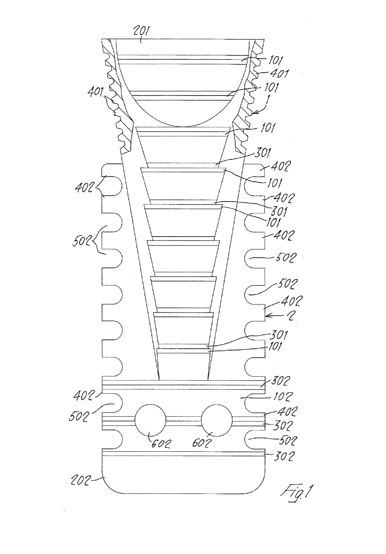
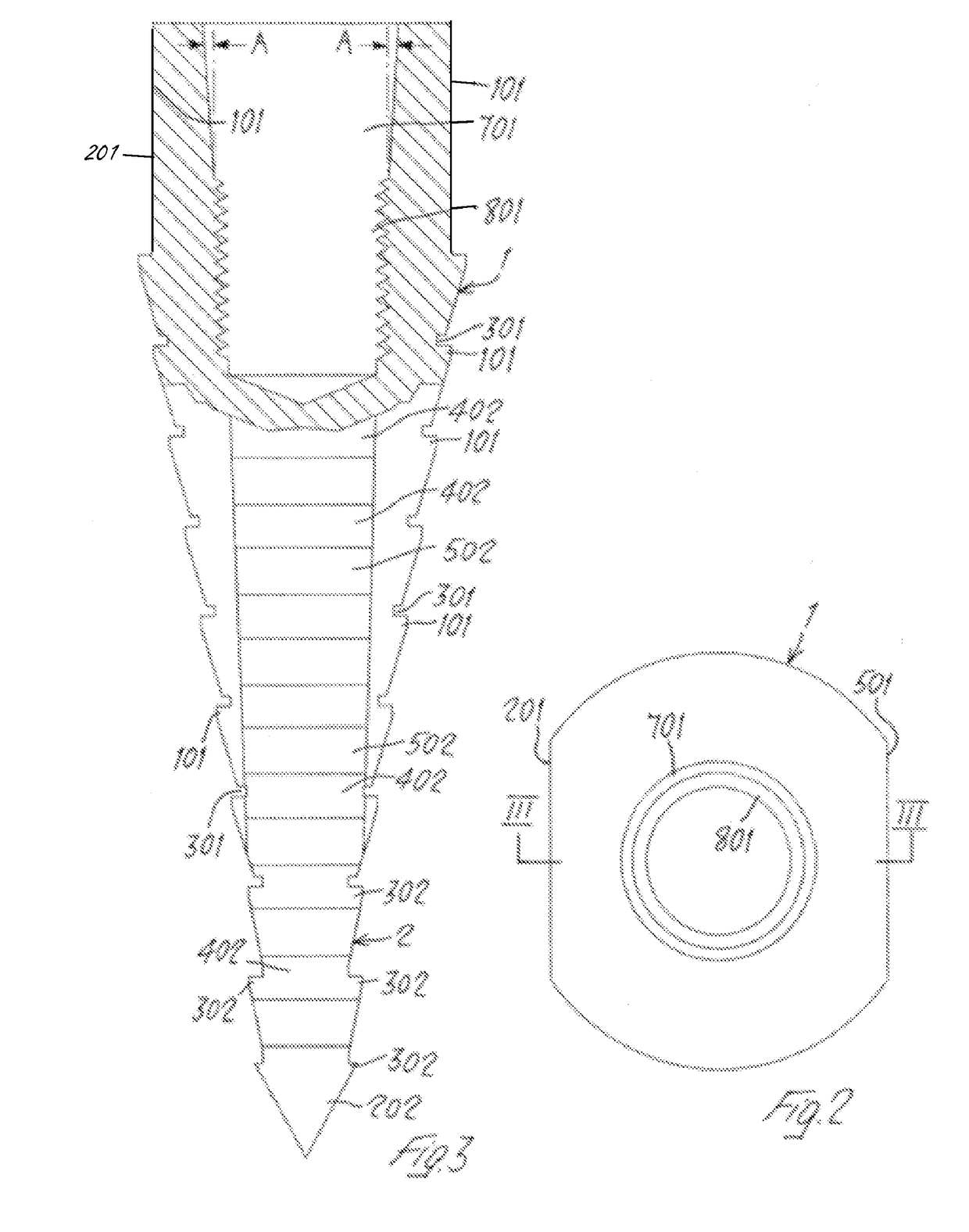
[0014]With reference to the accompanying drawings and with particular reference to FIG. 1 thereof, 1 denotes the central body, with a substantially conical or frustoconical shape, of the present dental implant according to the invention, while 2 denotes a rectangular or square blade which is formed as from a certain height of the central body 1 and is positioned along a longitudinal mid-plane of said central body. This blade 2 comprises an end part 102 which extends at the bottom beyond the end of the central body 1 with a smaller cross-section and is provided at the end with a transverse tip 202 which has edges which are suitably chamfered in order to avoid undesirable damage to the patient's bone. Said rectangular blade 2 and said central body 1 thus give the present implant a substantially wedge-like form. A series of transverse teeth 101 located on two diametrically opposite surfaces of said central body 1—in this case on the front surface and on the rear surface thereof—are for...

second embodiment

[0022]The blade-like form of this second embodiment of the present implant, which is therefore advantageously designed with a small thickness, allows the same to be used in a simple and efficient manner in bone zones with a very small bone volume or in zones with atrophic crests. The simplicity with which the present implant can be inserted also reduces advantageously the surgery time for installation of the implant, the possibility of infections and any undesirable damage to the bone.

[0023]The present implant is advantageously compatible with the stump pins of the most well-known implant manufacturers in the sector (31, SwissPlus, Branemark, Straumann, Zimmer) owing to an intermediate connection (between implant and stump) which may, in some cases, be separate from the implant and therefore be able to be added thereto during stages following that of implant insertion and, in other cases, may even already form part of the implant itself (thus forming a single piece), thereby creatin...


PUM


Abstract

Dental implant, having a central body (1) with a substantially conical or frustoconical shape and having, extending from the end with a larger cross-section, a connection seat (701) able to receive a stump pin; this central body (1) is provided with a blade (2) positioned in a longitudinal mid-plane of said central body (1) and has a length so as to protrude beyond the end of said central body (1) which has a smaller cross-section; said central body (1) and the blade (2) are able to give the implant a substantially wedge-like form able to expand the bone during insertion.

Description

[0001]The present invention relates to dental implants.BACKGROUND OF THE INVENTION[0002]As is known, when performing dental implants, pins are fixed onto the jaw or onto the upper jaw bone of the patient in predetermined positions. These implants are also provided at the top with a seat inside which stump pins or the like are fixed. There are cases where the thickness of the patient's bone in which the implant is to be performed is very small, for example from 2.5 mm to 6 mm, and in such cases insertion of the implant is very difficult since, in order to be able to insert the implant, it is required to perform complicated regenerative surgery using special bone grafts. Usually, a normal implant, which has a main body with a cylindrical cross-section, requires a thickness of the bone crest at least 2 mm greater than its diameter.SUMMARY OF THE INVENTION[0003]The object of the present invention is therefore to provide a dental implant which may be advantageously applied even in small-...

Claims


Application Information

Patent Timeline
Patent Type & Authority Applications(United States)
IPC IPC(8): A61C8/00
CPCA61C8/0045A61C8/0021A61C8/0019
Inventor VERCELLOTTI, TOMASOREBAUDI, ALBERTO
Owner REX IMPLANTS LLC
Learn More