
Gyroscopic Orbiter with Vertical Takeoff and Vertical Landing Capabilities

a technology of orbiter and vertical landing, applied in the field of aircraft, can solve the problems of wasteful vehicles designed for flight in the outer edges of the earth's atmosphere and space, neither cost-effective nor environmentally friendly,

Active Publication Date: 2017-03-30
HESSE THOMAS NORMAN
View PDF0 Cites 12 Cited by
  • Summary
  • Abstract
  • Description
  • Claims
  • Application Information

AI Technical Summary

Benefits of technology

The present invention is an aircraft that can transform from a vertical takeoff and landing position to a streamlined position for high-speed flight. It uses robotic and autonomous control to ensure safe, efficient, and pollution-free travel. The aircraft is designed to be durable and comfortable, with options for different environments and purposes of flight. It incorporates electric motor systems for efficient and reliable flight. The invention is a new class of intelligent aircraft that utilizes robotic and autonomous control to ensure safe, efficient, and pollution-free orbital travel. It uses clean burning propellants and / or electric power to recharge batteries during high-level descent from efficient flight altitudes or re-entry. The invention is a durable aircraft that provides a comfortable, safe, and immersive flight experience to users.

Problems solved by technology

Current designs for aircraft capable of achieving vertical takeoff and landing require large amounts of petroleum-based fuel, which is neither cost-effective nor environmentally friendly.
Further, vehicles designed for flight in the outer edges of the earth's atmosphere and in space are equally wasteful because such vehicles also require large amounts of fuel.

Method used


Image

  • Gyroscopic Orbiter with Vertical Takeoff and Vertical Landing Capabilities
  • Gyroscopic Orbiter with Vertical Takeoff and Vertical Landing Capabilities
  • Gyroscopic Orbiter with Vertical Takeoff and Vertical Landing Capabilities

Examples


Embodiment Construction

[0021]All illustrations of the drawings are for the purpose of describing selected versions of the present invention and are not intended to limit the scope of the present invention.

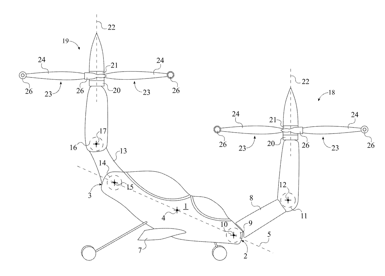
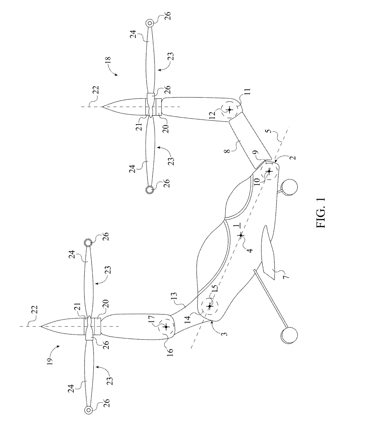
[0022]The present invention is a gyroscopic orbiter with vertical takeoff and vertical landing capabilities and is able to structurally reconfigure itself in midflight between a vertical takeoff or landing (VTOL) mode, a shuttle mode, and a high speed mode. As can be seen in FIG. 1, the present invention comprises a fuselage 1, a front boom 8, a front proximal hinge joint 9, the front distal hinge joint 11, a front propulsion unit 18, a port lateral fin 6, and a starboard lateral fin 7. The fuselage 1 is used to house passengers and cargo and provides the present invention with a central body to connect its other components. The front propulsion unit 18 is used to generate thrust for the present invention. The front boom 8 extends the front propulsion unit 18 away from the fuselage 1 so that the front pr...


PUM


Abstract

A gyroscopic orbiter with vertical takeoff and vertical landing capabilities can transition between different functional modes while in-flight. The orbiter typically includes a fuselage, a front boom, a front propulsion unit, a rear boom, and a rear propulsion unit. The front boom is mounted at two pivot points to a bow of the fuselage by the front boom. The rear boom is mounted at two pivot points to a stern of the fuselage by the rear boom. One functional mode is the vertical takeoff and landing mode, wherein the propulsion units are oriented parallel to each other and are directed upward. Another functional mode is the shuttle mode, wherein the propulsion units are oriented at an angle with each other, and the front propulsion unit is directed forward. Another functional mode is the high speed mode, wherein the propulsion units are oriented collinear with a roll axis of the fuselage.

Description

[0001]The current application is a continuation-in-part (CIP) application of a U.S. non-provisional application Ser. No. 15 / 063,507 filed on Mar. 7, 2016. The U.S. non-provisional application Ser. No. 15 / 063,507 claims a priority to a U.S. provisional application Ser. No. 62 / 128,860 filed on Mar. 5, 2016. The U.S. non-provisional application Ser. No. 15 / 063,507 was filed on Mar. 7, 2016 while Mar. 5, 2016 was on a weekend.FIELD OF THE INVENTION[0002]The present invention relates generally to an aircraft. More specifically, the present invention is an aircraft that is configurable in flight from a vertical takeoff and landing position to a streamlined position for high speed flight. Furthermore, the present invention may be used for orbital flight through the outer limits of the Earth's atmosphere and in-space.BACKGROUND OF THE INVENTION[0003]Vertical takeoff and landing capabilities are a widely sought after feature for aircraft. Current designs for aircraft capable of achieving ver...

Claims


Application Information

Patent Timeline
IPC IPC(8): B64G1/14B64C29/02B64G1/00B64C11/46B64G1/40B64C29/00B64C5/06
CPCB64G1/14B64C29/0033B64C29/02B64G1/002B64C11/46B64G1/40B64C5/06B64C25/32B64C27/18B64C27/605B64D27/026B64G1/006
Inventor HESSE, THOMAS NORMAN
Owner HESSE THOMAS NORMAN
Learn More