Touch-display panel and touch-display device

Active Publication Date: 2017-03-30
SHANGHAI TIANMA MICRO ELECTRONICS CO LTD +1
View PDF5 Cites 13 Cited by
  • Summary
  • Abstract
  • Description
  • Claims
  • Application Information

AI Technical Summary

Benefits of technology

[0009]With providing the dummy touch signal wires, the spacers are provided above the touch signal wires and the dummy touch signal wires so as to increase the flexibility of distribution of the spacers, and to solve the problem that the cell thickness i

Problems solved by technology

With respect to an integrated touch-display device, wires for touch signals are provided within the display area for transmitting touch signals to the touch electrodes, while the wires for the touch signals within display area m

Method used


Image

  • Touch-display panel and touch-display device
  • Touch-display panel and touch-display device
  • Touch-display panel and touch-display device

Examples


Embodiment Construction

[0021]Detailed description would be made on the present disclosure in connection with the drawings and the embodiments. It should be appreciated that, the embodiments described herein are merely used for explanation of related disclosure, rather than for limitation on the present disclosure. Furthermore, it should be noted that, only parts related to the present disclosure are shown in the drawings for convenience of description.

[0022]It should be noted that, the embodiments and features of the embodiments of the present disclosure may be combined with each other without conflicting with each other. In the following, detailed description is made on the present disclosure in connection with the drawings.

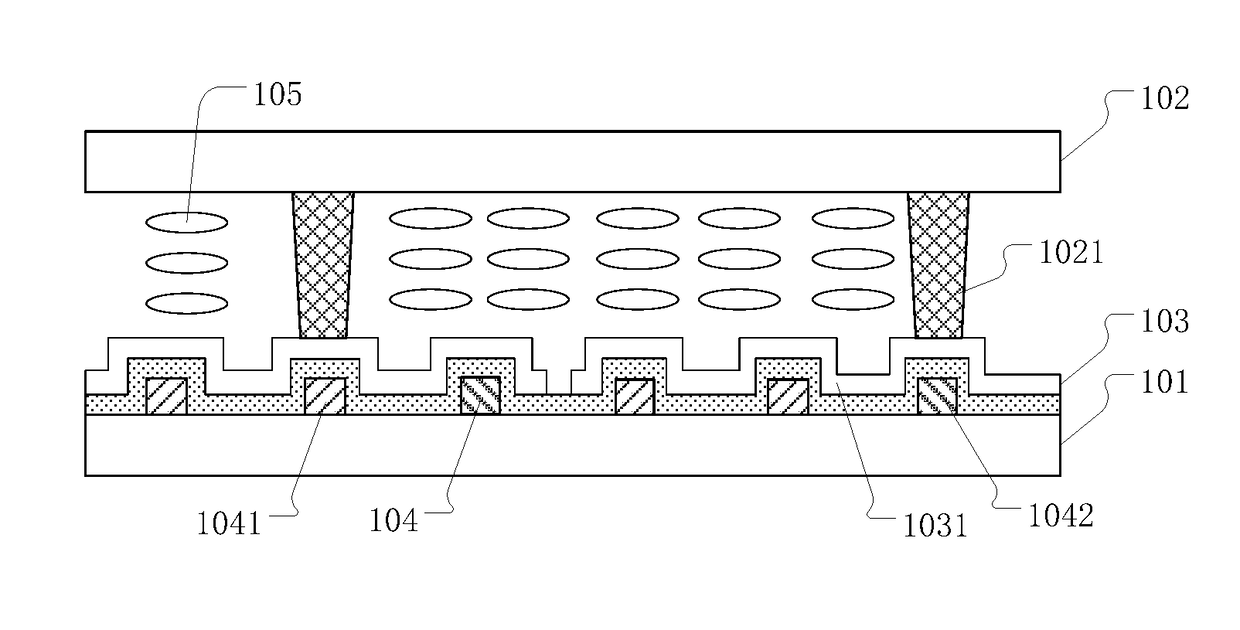
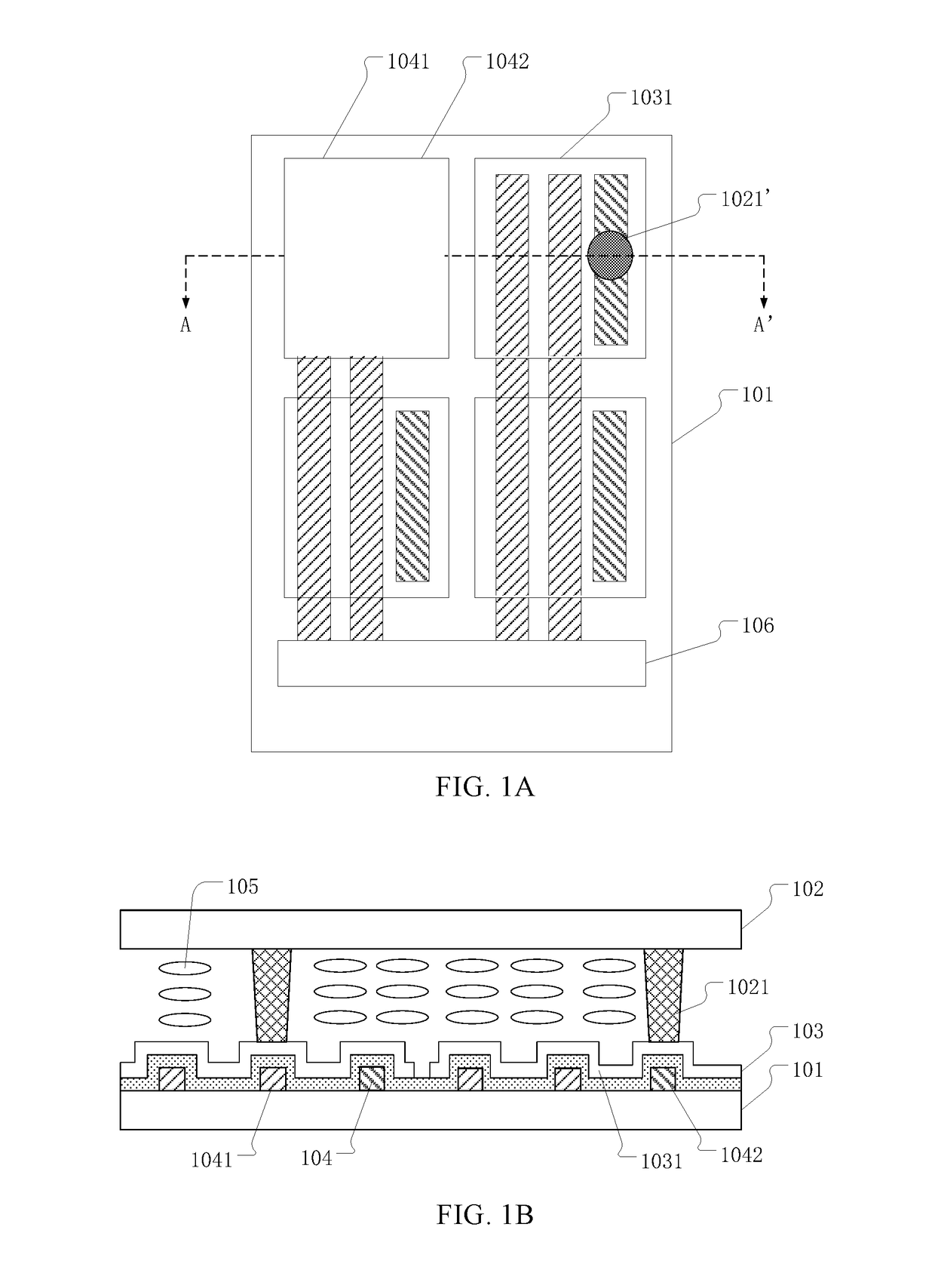
[0023]FIG. 1A is a schematic view of an embodiment of the touch-display panel according to the present invention, and FIG. 1B is a cross-section view taken along line AA′ of FIG. 1A. Referring to FIG. 1A and FIG. 1B, a touch-display panel includes a first substrate 101 and a second su...


PUM


Abstract

The present disclosure provides a touch-display panel including a first substrate and a second substrate; a touch electrode layer provided on the first substrate and including a plurality of touch electrodes; a touch signal wire layer including a plurality of touch signal wires. The touch signal wire layer further includes a plurality of dummy touch signal wires. A plurality of spacers is provided on a surface of the second substrate facing the first substrate, wherein the plurality of spacers have a first orthographic projection on the plane of the touch signal wire layer, and the orthographic projection is overlapped with said touch signal wires or the dummy touch signal wires. The touch-display panel provides dummy touch signal wires and the first orthographic projections of the spacer on the plane of the touch signal wire layer are overlapped with the touch signal wires or dummy touch signal wires.

Description

CROSS-REFERENCES TO RELATED APPLICATIONS[0001]This application claims priority of Chinese Patent Application No. 201610297874.7, filed on May 6, 2016, the entire contents of which are hereby incorporated by reference.BACKGROUND[0002]As the rapid developments of display technology, touch panels have been very popular all over people's life. As the developments of capacitive touch-display technology, touch electrodes may be directly integrated inside a display panel so as to be integrated with the existed layer structure inside the display panel, thereby significantly lowering the manufacturing cost, increasing the productivity, and reducing the thickness of the panel.[0003]The current liquid crystal display (LCD) device includes a color filter substrate and an array substrate opposed to each other, and a liquid crystal layer between the color filter substrate and the array substrate. There is a frame adhesive provided between the color filter substrate and the array substrate so as t...

Claims


Application Information

Patent Timeline
IPC IPC(8): G06F3/041G02F1/1343G02F1/1339G06F3/044G02F1/1333
CPCG06F3/0412G06F3/044G06F3/0416G02F1/13338G02F1/13394G02F2201/121G02F1/134309G06F2203/04111G02F2001/13398G02F2001/13396G02F1/133345G06F3/0445G06F3/04164G02F1/13396
Inventor DING, HONGDU, LINGXIAOLI, GUJUN
Owner SHANGHAI TIANMA MICRO ELECTRONICS CO LTD
Why Eureka
Try Eureka