
Tubular Lithium Battery

a lithium battery, tubular technology, applied in the direction of batteries, sustainable manufacturing/processing, cell components, etc., can solve the problems of affecting the sealing condition of the package, the inability to wind the soft package, and the electrode wounding of the lithium battery, so as to increase the capacity of the battery

Active Publication Date: 2017-03-30
PROLOGIUM TECH +1
View PDF1 Cites 38 Cited by
  • Summary
  • Abstract
  • Description
  • Claims
  • Application Information

AI Technical Summary

Benefits of technology

The present invention provides a tubular lithium battery that can be adjusted for different operation needs and increased capacity by adding or connecting power supply units in series or parallel. The battery's terminals can be arranged in different ways using different designs, and the winding direction of the power supply unit and packaging unit can also affect the position of the battery's terminals.

Problems solved by technology

Apparently, the conventional lithium battery can only make the electrodes, separators and even the electrolytes wound.
Even if the soft lamination foil is exerted, it is still impossible to wind the soft package after the foil has been well-sealed.
The other reason is that to wind the well-sealed battery would damage the sealing condition of the package such as breaking the vacuum of the sealing of the package.
Once the moisture and oxygen in the environment penetrate into the battery through the broken holes of the sealing edges, the electrodes, electrolyte and all the chemicals would be damaged due to the severe oxidation-reduction reactions.
Besides, the battery having certain size and shape would limit the possibilities of varying the design and size of the electronic device.
For instance, in the electronic device, a space must be reserved for placing the battery and that would limit the design and size of the electronic device.
Along with the trends of the development of the electronic device, the device having thinner and lighter characteristics cannot be achieved if the conventional battery having an un-changeable shape is exerted.

Method used


Image

  • Tubular Lithium Battery
  • Tubular Lithium Battery
  • Tubular Lithium Battery

Examples


Embodiment Construction

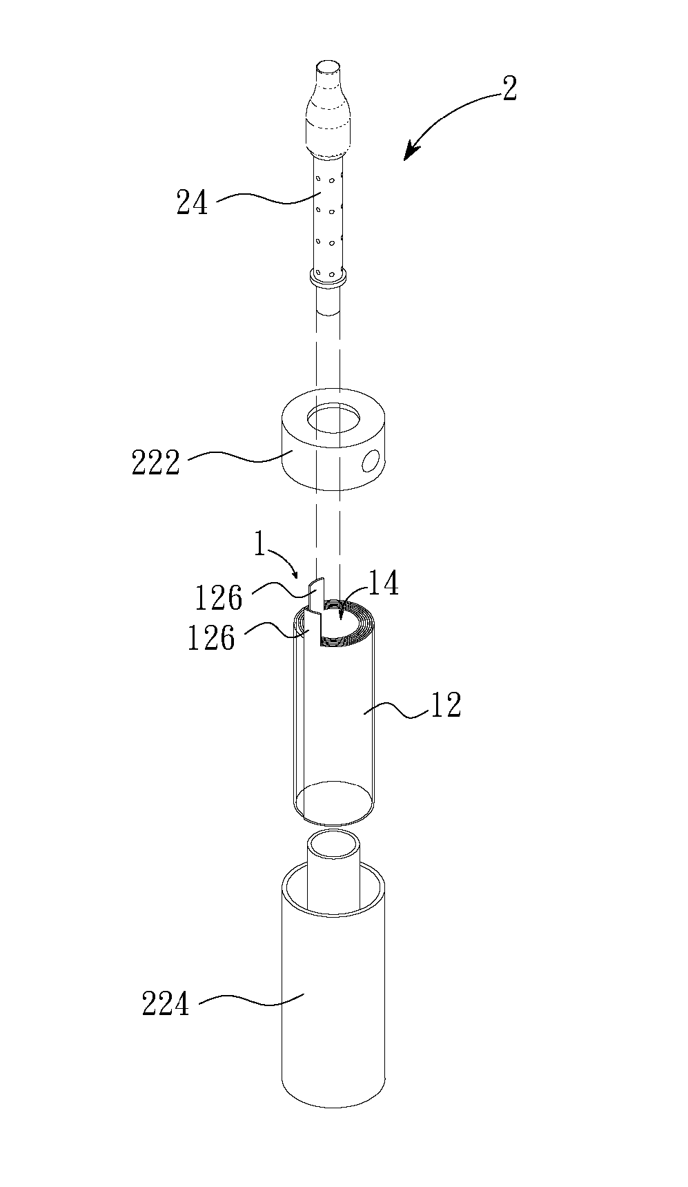
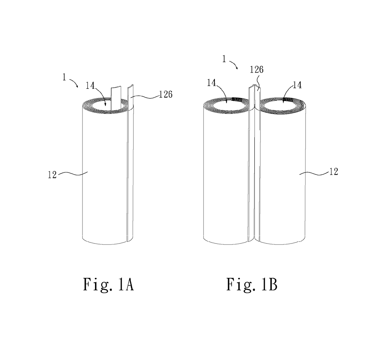
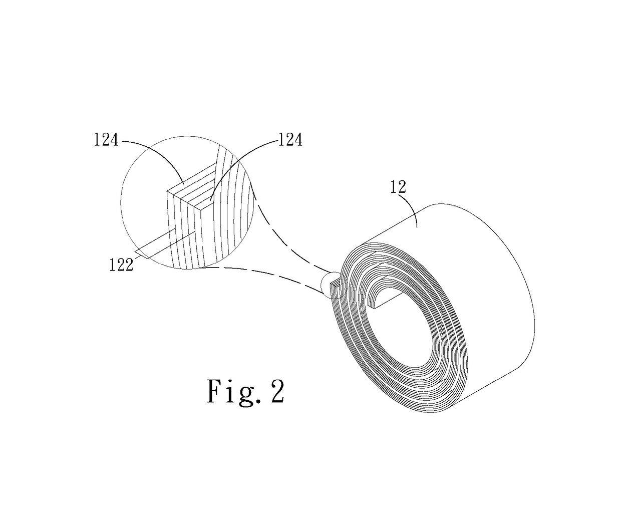
[0021]Please refer to FIG. 1A, it is a schematic structural view of a tubular lithium battery of the present invention. The tubular lithium battery 1 includes a body 12 and at least one hollow channel 14. The hollow channel 14 is positioned inside the body 12. The body 12 has at least one power supply unit 122, at least one packaging unit 124 and at least two terminals 126. The power supply unit 122 is packed by the packaging unit 124 and is electrically connected to the terminals 126. The packaging unit 124 may entirely isolate the chemicals of the power supply unit 122 from the outer environment. One of the terminal 126 is a positive terminal and the other terminal 126 is a negative terminal. The body 12 is formed by winding the power supply unit 122 and the packaging unit 124 at the same time, that is, the body 12 of the tubular lithium battery 1 is the wound power supply unit 122 and the wound packaging unit 124 as a whole and is configured as a hollow column. In this embodiment...


PUM


Abstract

The invention discloses a tubular lithium battery. The tubular lithium battery comprises at least a tubular body and a hollow channel. The body has at least one power supply unit, at least one packaging unit and at least two terminals. The power supply unit is packed via the packaging unit and is electrically connected to the terminals. The power supply unit and the packaging unit are wound as a whole. The hollow channel, which is positioned inside the body, is formed by winding the power supply unit and the packaging unit. The orientations and the positions of the terminals may be various due to locating in different positions of the power supply unit as well as winding the power supply unit and the packaging unit toward different directions, so that the electronic device exerting the tubular lithium battery disclosed in the present invention can be designed in various ways.

Description

CROSS REFERENCE TO RELATED APPLICATIONS[0001]This Non-provisional application claims priority under 35 U.S.C. §119(a) on Patent Application No. 104131973 filed in Taiwan, Republic of China on Sep. 30, 2015, the entire contents of which are hereby incorporated by reference.BACKGROUND[0002]1. Technical Field[0003]The present invention relates to a lithium battery. Specifically, the present invention relates to a tubular lithium battery, which is wound with its package to form a hollow column.[0004]2. Description of Related Art[0005]Conventionally, no matter for the so-called winding-type battery or for the so-called jelly-roll-type battery, the object for winding only includes the electrodes and separator. For some solid-state battery, the electrolyte may be wound with the electrodes and separator as a whole. As for the package of the battery, the common configurations of the package include the rigid metal can and the soft lamination foil. For instance, the daily used 18650 battery c...

Claims


Application Information

Patent Timeline
IPC IPC(8): H01M2/02A24F47/00H01M10/04H01M10/0587H01M10/0525A24F40/40
CPCH01M2/022H01M10/0587H01M10/0525H01M2002/0205A24F47/008H01M2220/30H01M10/0422H01M10/052Y02E60/10A24F40/40H01M50/107H01M50/213Y02P70/50
Inventor YANG, SZU-NAN
Owner PROLOGIUM TECH
Learn More