Methods and systems for hotspot detection

a hotspot detection and hotspot technology, applied in image enhancement, optical radiation measurement, instruments, etc., can solve the problems of cracker external wall hot spots, eventual burnout, loss of production capacity, etc., and achieve the effect of improving monitoring and alerting industrial processes

Active Publication Date: 2017-03-30
QUANTUM IR TECH LLC
View PDF9 Cites 24 Cited by
  • Summary
  • Abstract
  • Description
  • Claims
  • Application Information

AI Technical Summary

Problems solved by technology

Over time, this insulation may break down, leading to “hot spots” on the external walls of the cracker, and eventual burn through.
Hot spots and burn through of cracker structural components result in lost production capacity and substantial losses in revenue as a result.

Method used


Image

  • Methods and systems for hotspot detection
  • Methods and systems for hotspot detection
  • Methods and systems for hotspot detection

Examples


Embodiment Construction

” one will understand how the subject matter described herein may be utilized to improve monitoring and alerting of industrial processes.

BRIEF DESCRIPTION OF THE DRAWINGS

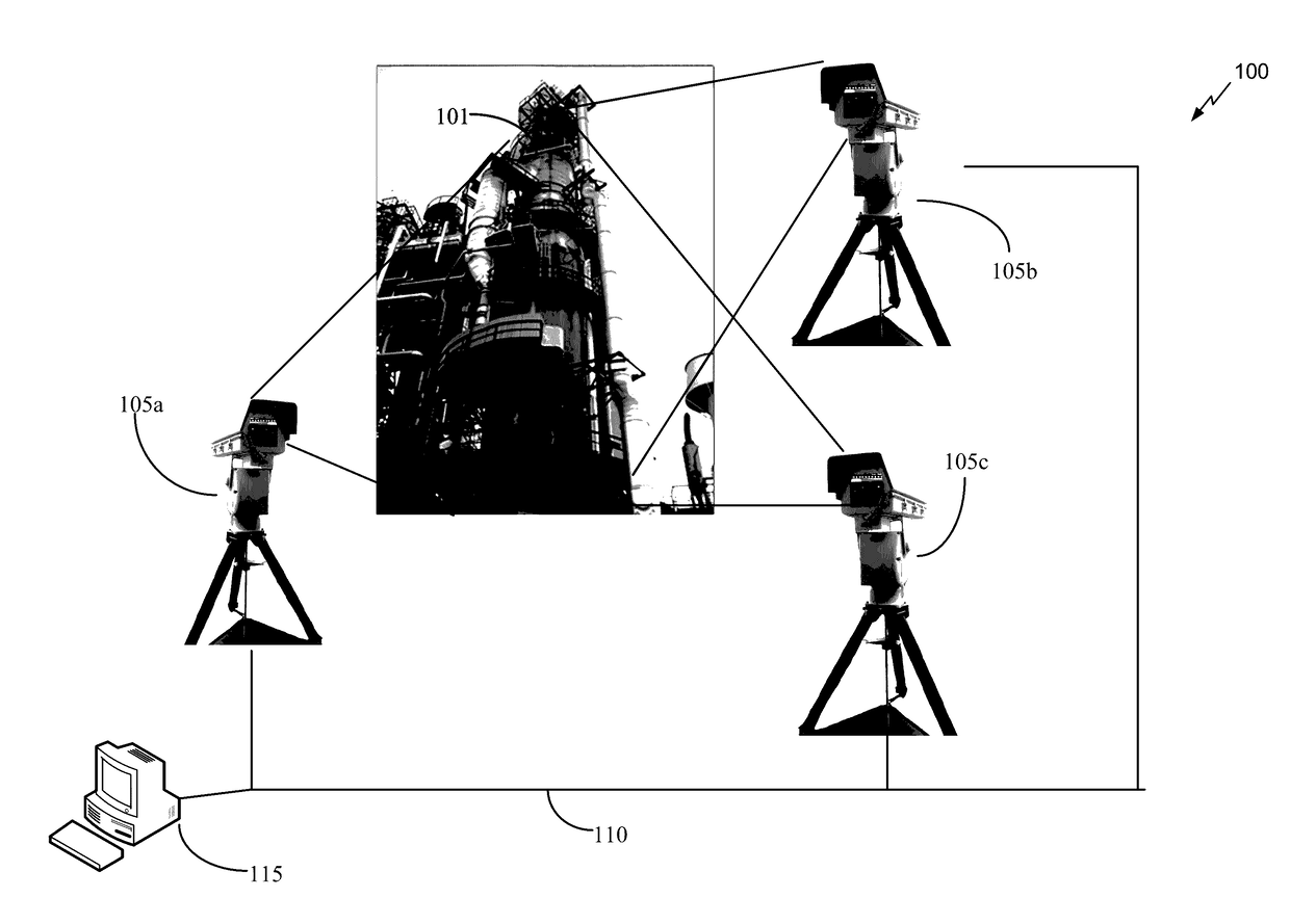
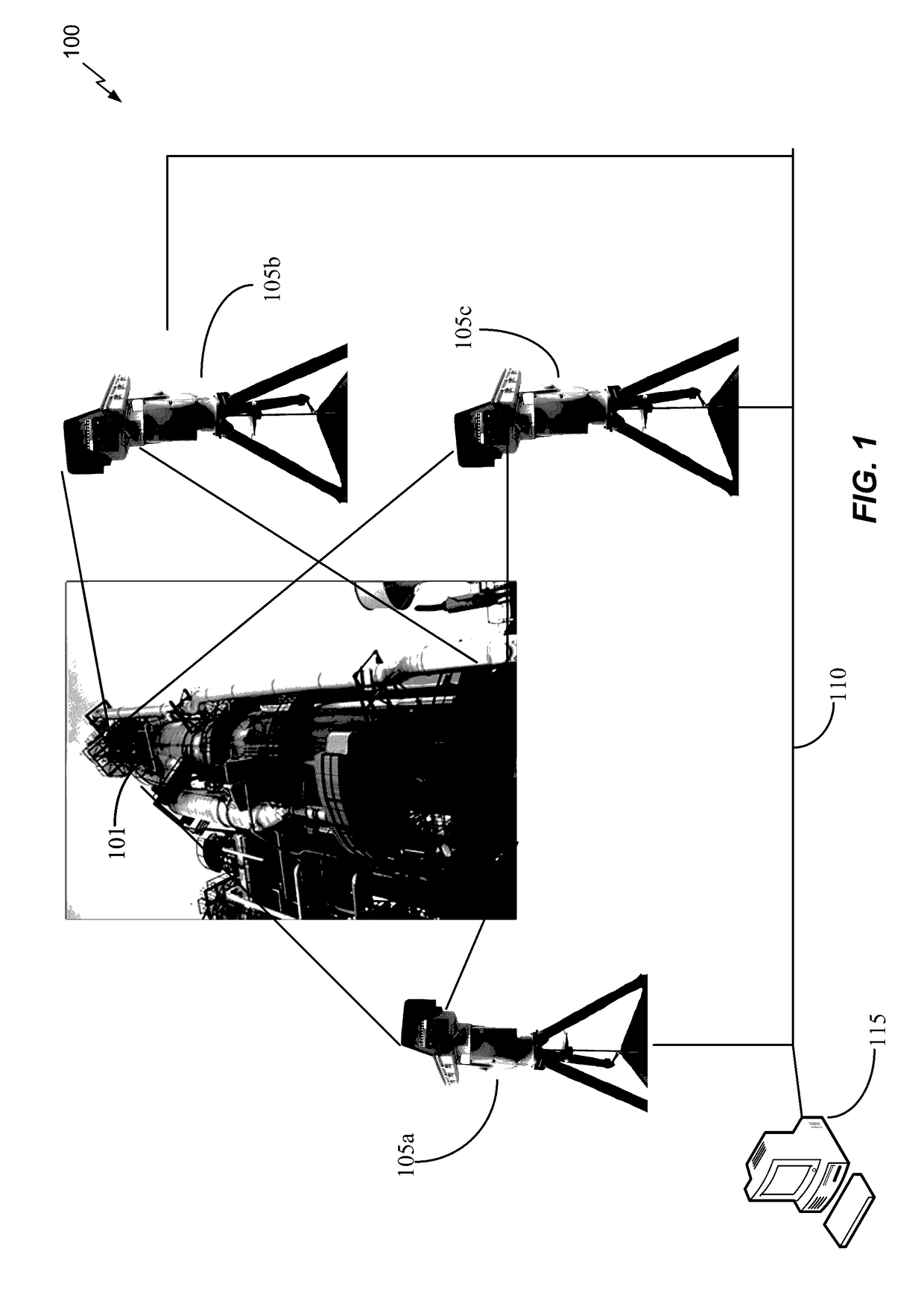
[0006]FIG. 1 is an overview diagram of a system for monitoring an industrial process, in this case, a petrochemical cracker.

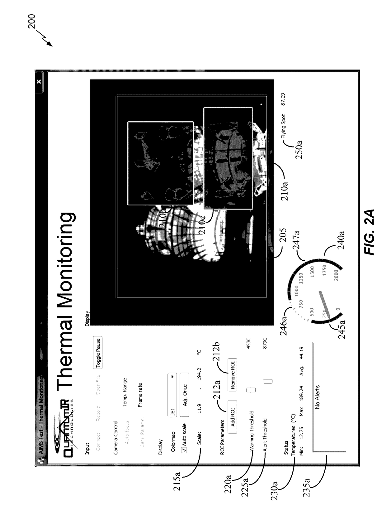
[0007]FIG. 2A is a user interface for monitoring temperatures of one or more regions of interest.

[0008]FIG. 2B shows another view of the user interface 200 with a different region of interest selected than in FIG. 2A.

[0009]FIG. 2C shows a modified version of the user interface 200′ with region of interest 210c selected.

[0010]FIG. 2D shows another embodiment of a user interface.

[0011]FIG. 2E shows another embodiment of a user interface.

[0012]FIG. 2F is a data flow for data received from a plurality of imaging sensors.

[0013]FIG. 2G shows an alternative data flow 2500 for data received from multiple imaging sensors.

[0014]FIG. 3 is a diagram showing one embodiment of the system of FIG. 1.

[0015]FIG....


PUM


Abstract

Methods and systems for monitoring an industrial process are disclosed. Some aspects of the system arrange multiple imaging sensors to image machinery associated with an industrial process. Regions of interest within images acquired by the multiple imaging sensors may be monitored for abnormal thermal conditions, and alerts generated as needed. Alerts may also be generated if temperatures within a region of interest exceed thresholds associated with that region of interest. Each region of interest may be independently monitored and have individualized alerting thresholds. In some aspects, images from the multiple imaging sensors may be stitched together, with the regions of interest based on the stitched image. In other aspects, regions of interest within images from separate imaging sensors may be linked together so as to share at least common alerting thresholds.

Description

CROSS REFERENCE TO RELATED APPLICATIONS[0001]This application claims priority to U.S. Provisional Application No. 62 / 186,262, filed Jun. 29, 2015, and entitled “INFRARED IMAGING SYSTEMS AND METHODS FOR THERMAL OBJECT MONITORING.” The disclosure of this prior application is considered part of this application, and is hereby incorporated by reference in its entirety.FIELD OF THE INVENTION[0002]The present application relates generally to computer analysis of thermal images. In particular, disclosed are methods and systems for generating alerts when particular regions of a monitored image exceed temperature parameters.BACKGROUND[0003]Petrochemical cracking is used to break up large hydrocarbon molecules into smaller molecules. This process may be performed with or without a catalyst. In one form of cracking called fluid catalytic cracking, hydrocarbons are mixed with a very fine catalyst powder of aluminum oxide and silicon dioxide. The whole mixture is then blown like a liquid through...

Claims


Application Information

Patent Timeline
Patent Type & Authority Applications(United States)
IPC IPC(8): H04N7/18G06T7/11G01J5/50H04N5/33G08B21/18G01J5/00
CPCH04N7/181H04N5/33G01J2005/0077G01J5/505G06T7/11G08B21/182G01J5/0037G01J5/0066G01J5/026G06T7/0004G06T2207/10048G06T2207/30108G06T3/4038
Inventor ISRAELSON, MARK C.
Owner QUANTUM IR TECH LLC
Why Eureka
Try Eureka