Apparatus for and method of range sensor based on direct time-of-flight and triangulation

a range sensor and time-of-flight technology, applied in the direction of generating/distributing signals, distance measurement, pulse technique, etc., can solve the problems of projected pattern deformation or displacement, and achieve the effect of improving vision and improving the performance of an autonomous navigation system

Active Publication Date: 2017-04-06
SAMSUNG ELECTRONICS CO LTD
View PDF2 Cites 33 Cited by
  • Summary
  • Abstract
  • Description
  • Claims
  • Application Information

AI Technical Summary

Benefits of technology

[0011]Another aspect of the present disclosure provides an apparatus for and a method of improved vision for drivers under difficult conditions (e.g., low light, bad weather, strong ambient light, etc.).
[0012]Another aspect of the present disclosure provides an apparatus for and a method of improving the performance of an autonomous navigation system.

Problems solved by technology

The projected pattern may get deformed or displaced when striking the surface of the 3D object.

Method used


Image

  • Apparatus for and method of range sensor based on direct time-of-flight and triangulation
  • Apparatus for and method of range sensor based on direct time-of-flight and triangulation
  • Apparatus for and method of range sensor based on direct time-of-flight and triangulation

Examples


Embodiment Construction

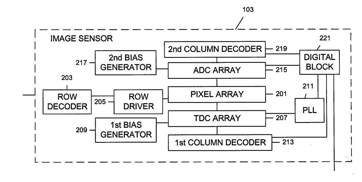
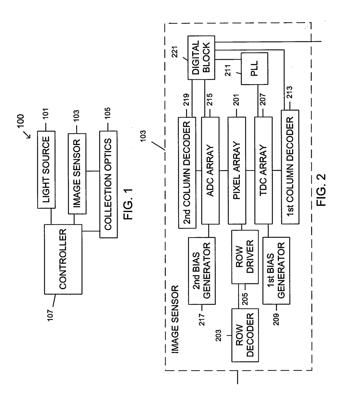
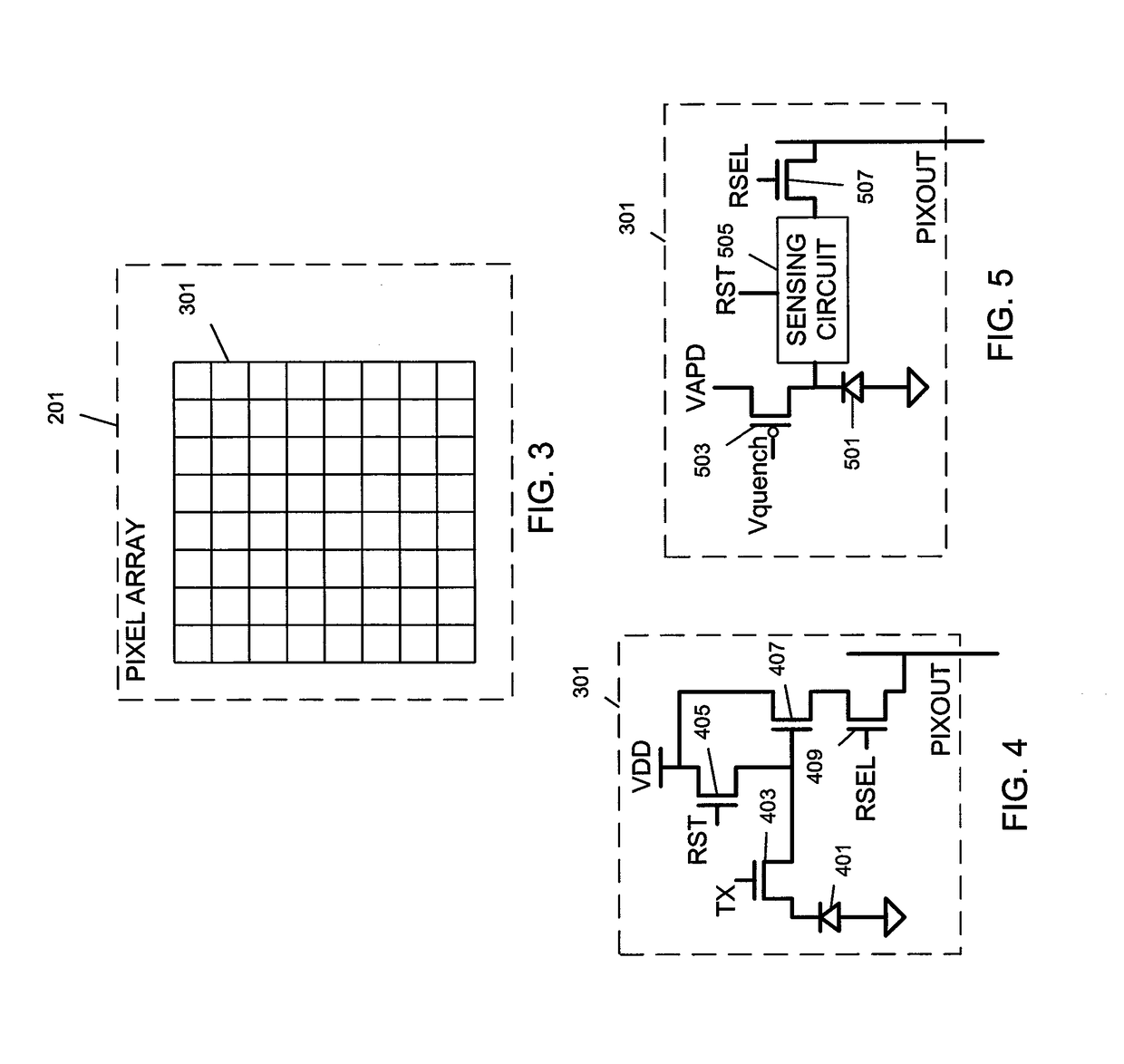
[0028]Hereinafter, embodiments of the present disclosure are described in detail with reference to the accompanying drawings. It should be noted that the same elements will be designated by the same reference numerals although they are shown in different drawings. In the following description, specific details such as detailed configurations and components are merely provided to assist the overall understanding of the embodiments of the present disclosure. Therefore, it should be apparent to those skilled in the art that various changes and modifications of the embodiments described herein may be made without departing from the scope and spirit of the present disclosure. In addition, descriptions of well-known functions and constructions are omitted for clarity and conciseness. The terms described below are terms defined in consideration of the functions in the present disclosure, and may be different according to users, intentions of the users, or customs. Therefore, the definition...


PUM


Abstract

A range sensor and a method thereof. The range sensor includes a light source configured to project a sheet of light at an angle within a field of view (FOV); an image sensor offset from the light source; collection optics; and a controller connected to the light source, the image sensor, and the collection optics, and configured to determine a range of a distant object based on direct time-of-flight and determine a range of a near object based on triangulation. The method includes projecting, by a light source, a sheet of light at an angle within an FOV; offsetting an image sensor from the light source; collecting, by collection optics, the sheet of light reflected off objects; and determining, by a controller connected to the light source, the image sensor, and the collection optics, a range of a distant object based on direct time-of-flight and a range of a near object based on triangulation simultaneously.

Description

PRIORITY[0001]This application claims priority under 35 U.S.C. §119(e) to a U.S. Provisional Patent Application filed on Oct. 6, 2015 in the United States Patent and Trademark Office and assigned Ser. No. 62 / 237,777, the entire contents of which are incorporated herein by reference.BACKGROUND OF THE DISCLOSURE[0002]Field of the Disclosure[0003]The present disclosure relates generally to an apparatus for and a method of a range sensor, and more particularly, to an apparatus for and a method of a range sensor based on direct time-of-flight (TOF) and triangulation simultaneously.[0004]Description of the Related Art[0005]Three-dimensional (3D) imaging systems are increasingly being used in a wide variety of applications such as, for example, high speed 3D imaging systems for advanced driver assistant systems (ADAS) and high speed 3D imaging systems for autonomous navigation.[0006]Existing 3D imaging technologies may include, for example, the TOF based range imaging, stereo vision system...

Claims


Application Information

Patent Timeline
Patent Type & Authority Applications(United States)
IPC IPC(8): G01S17/08
CPCG01S17/08H03K5/135G01S17/10G06F1/04G01S17/48G01S7/487G01S7/4863H04N5/33G01C3/10G01D21/02H04N23/56H04N25/767H04N25/77H04N25/75G01S7/4861G01S7/4876H03K3/012H03K3/0372H03K3/356052H03K3/356147H03K17/30H03K19/0013H03K19/0016
Inventor WANG, YIBING MICHELLE
Owner SAMSUNG ELECTRONICS CO LTD
Why Eureka
Try Eureka