
Movement control apparatus for heliostat device

a technology of heliostat and movement control mechanism, which is applied in the direction of lighting and heating apparatus, instruments, etc., can solve the problems of mechanical errors, disadvantages of current movement control mechanism, and difficulty in operation or responding to light, and achieve the effect of greater torqu

Inactive Publication Date: 2017-04-13
WANG CHENGWEI +1
View PDF0 Cites 7 Cited by
  • Summary
  • Abstract
  • Description
  • Claims
  • Application Information

AI Technical Summary

Benefits of technology

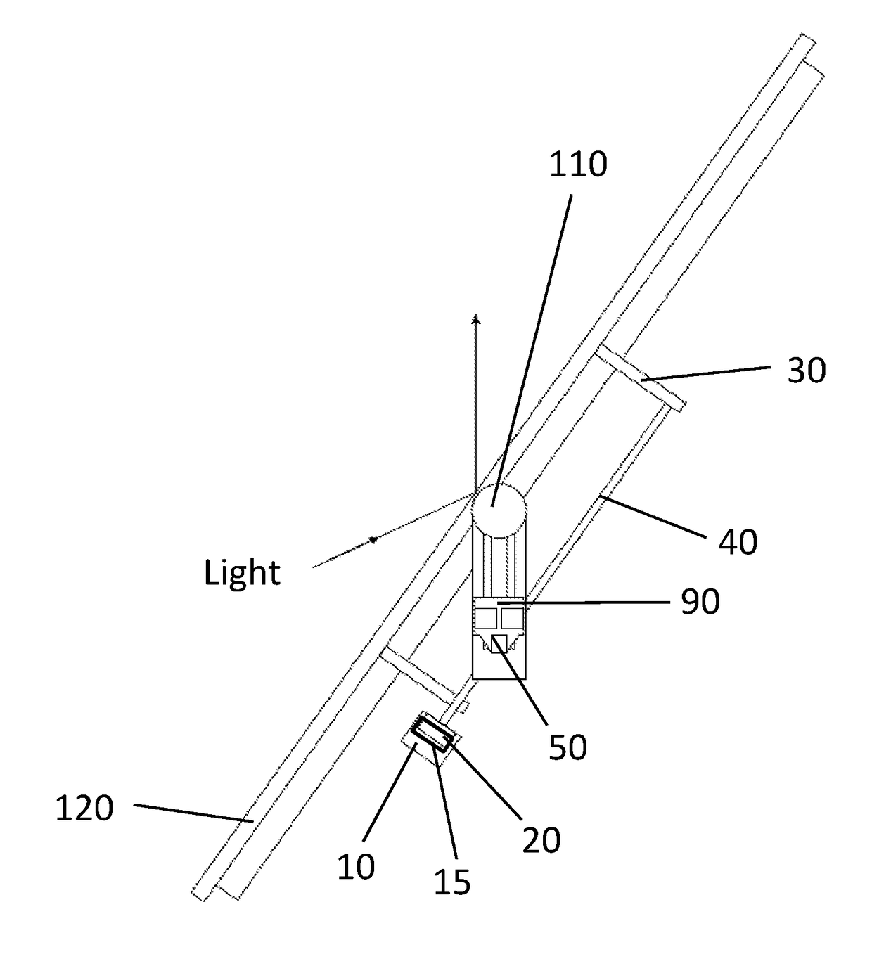
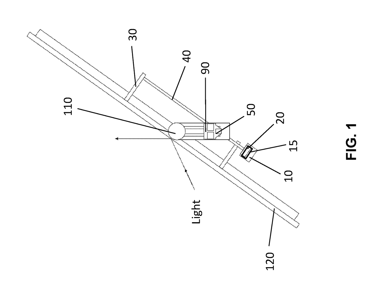
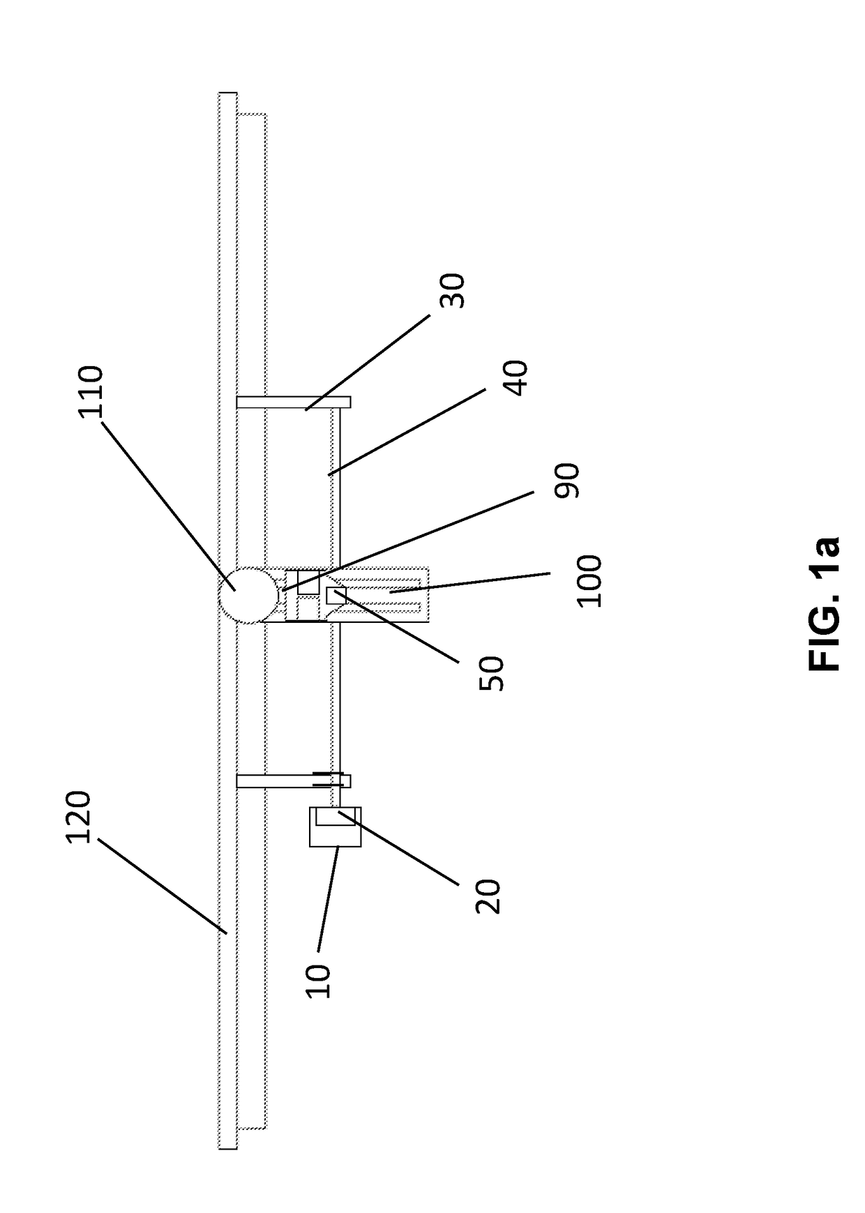
The present invention provides a movement control apparatus for a heliostat device that can eliminate mechanical errors during movement. It includes a rigid structure with two supporting frames and a ball screw secured on the frames to significantly reduce mechanical errors. The apparatus uses a step motor and decelerating motor to generate torque and drive the screw shaft to rotate, which in turn drives the nut to travel along the screw shaft. This rigid structure ensures that the torque received by the ball screw assembly is almost completely transformed to the energy for the nut to travel along the screw shaft. The movement of the nut can further drive the moving shaft to move in a linear manner on the sliding rail.

Problems solved by technology

However, current movement control mechanism may be disadvantageous because current movement control mechanism is either programmed or controlled by sensors, which is difficult to operate or respond to the light.
More importantly, mechanical errors may be generated and accumulated to adversely affect the positioning of the heliostat device.

Method used


Image

  • Movement control apparatus for heliostat device
  • Movement control apparatus for heliostat device
  • Movement control apparatus for heliostat device

Examples


Embodiment Construction

[0017]The detailed description set forth below is intended as a description of the presently exemplary device provided in accordance with aspects of the present invention and is not intended to represent the only forms in which the present invention may be prepared or utilized. It is to be understood, rather, that the same or equivalent functions and components may be accomplished by different embodiments that are also intended to be encompassed within the spirit and scope of the invention.

[0018]Unless defined otherwise, all technical and scientific terms used herein have the same meaning as commonly understood to one of ordinary skill in the art to which this invention belongs. Although any methods, devices and materials similar or equivalent to those described can be used in the practice or testing of the invention, the exemplary methods, devices and materials are now described.

[0019]All publications mentioned are incorporated by reference for the purpose of describing and disclos...


PUM


Abstract

A movement control apparatus for a heliostat device may include a step motor, a decelerating motor, a ball screw assembly, a nut, a connecting shaft, and a linear moving shaft. In one embodiment, the nut is movably connected with the ball screw assembly and is secured on a first connecting board and a second connecting board through the connecting shaft. The nut is driven by the ball screw assembly to travel along the screw shaft and since the nut is connected to the connecting boards through the connecting shaft, and the connecting boards are connected to the moving shaft, the movement of the nut can further drive the connecting shaft to rotate to drive the moving shaft to move in a linear manner on the sliding rail to rotate a mirror assembly of the heliostat around a post.

Description

CROSS-REFERENCE TO RELATED APPLICATIONS[0001]This application claims priority under 35 U.S.C. §119 (e) to U.S. Provisional Patent Application Ser. No. 62 / 241,066, filed on Oct. 13, 2015, the entire contents of which are hereby incorporated by reference.FIELD OF THE INVENTION[0002]The present invention relates to a heliostat device for a solar power panel, and more particularly to a movement control mechanism of the heliostat device.BACKGROUND OF THE INVENTION[0003]Solar power generation technology, which converts solar energy into heat and then converts heat into electricity by focusing solar energy and collecting heat, is one of the most prospective solar energy utilization modes, and a heliostat is used for focusing and reflecting sunlight.[0004]More specifically, the heliostat is a mirror device for locating the sunlight on a target accurately, and is usually used as a beam-condensing component in a solar illuminating apparatus or a solar thermal power generation system. In a tow...

Claims


Application Information

Patent Timeline
Patent Type & Authority Applications(United States)
IPC IPC(8): F16H25/20G02B7/183G02B26/08
CPCF16H25/20F16H2025/2043G02B7/183G02B26/0816F24S30/422F24S30/452F24S2030/11F24S2030/13F24S2030/19Y02E10/47
Inventor WANG, CHENGWEIWANG, ZHIMING
Owner WANG CHENGWEI
Learn More