Actuator with ball screw drive

a technology of ball screw drive and actuator, which is applied in the direction of gearing, building locks, constructions, etc., can solve the problems of preventing larger motors from fitting, affecting the performance of the actuator, and affecting the operation of the actuator

Active Publication Date: 2017-04-13
COMMAND ACCESS TECH INC
View PDF2 Cites 12 Cited by
  • Summary
  • Abstract
  • Description
  • Claims
  • Application Information

AI Technical Summary

Problems solved by technology

Because of the high contact area required in this type of leadscrew, the friction losses are generally very high.
However, larger motors and / or finer pitches cannot always satisfy the requirements for each exit device.
Size limitations may prevent larger motors from fitting within the enclosed mechanism case.
Finer thread pitches create several other problems.
First, the finer pitch often results in a slower actuation time.
More problematic however, is the requirement for the springs within the device to return the leadscrew to the starting point for “fail-safe” operation.
Because of the fail-safe requirement, driving the motor in reverse to lock the latch would not be possible.
The drive forces of the acme, or a similar style lead screw, is further complicated by the fact that the friction loss characteristics are different when the screw is “back-driven”.
As a thread pitch is made finer, the friction losses increase, nearly exponentially, to the point that the screw can no longer be back driven.
All of these constraints often lead to an impossibility of driving an exit device with a motor and lead screw within the existing specified enclosure constraints.

Method used


Image

  • Actuator with ball screw drive
  • Actuator with ball screw drive
  • Actuator with ball screw drive

Examples


Embodiment Construction

[0017]In the following detailed description and in the several figures of the drawing, like elements are identified with like reference numerals. The figures are not to scale, and relative feature sizes may be exaggerated for illustrative purposes.

[0018]One exemplary aspect of the invention is an electrified latch pullback system for new and retrofit applications. The system allows for centrally located power supplies and trouble free operation during “continuously on” conditions. The system may be provided as a modification kit for an existing exit device, or as part of an exit device.

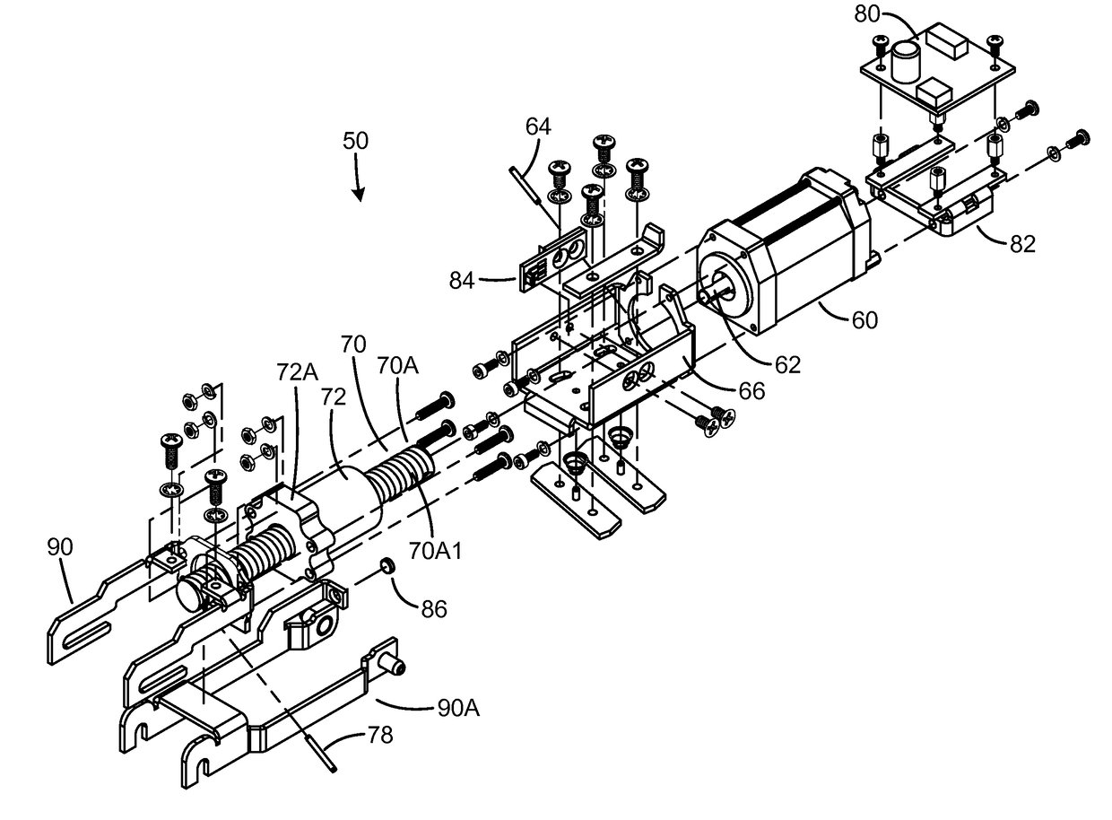
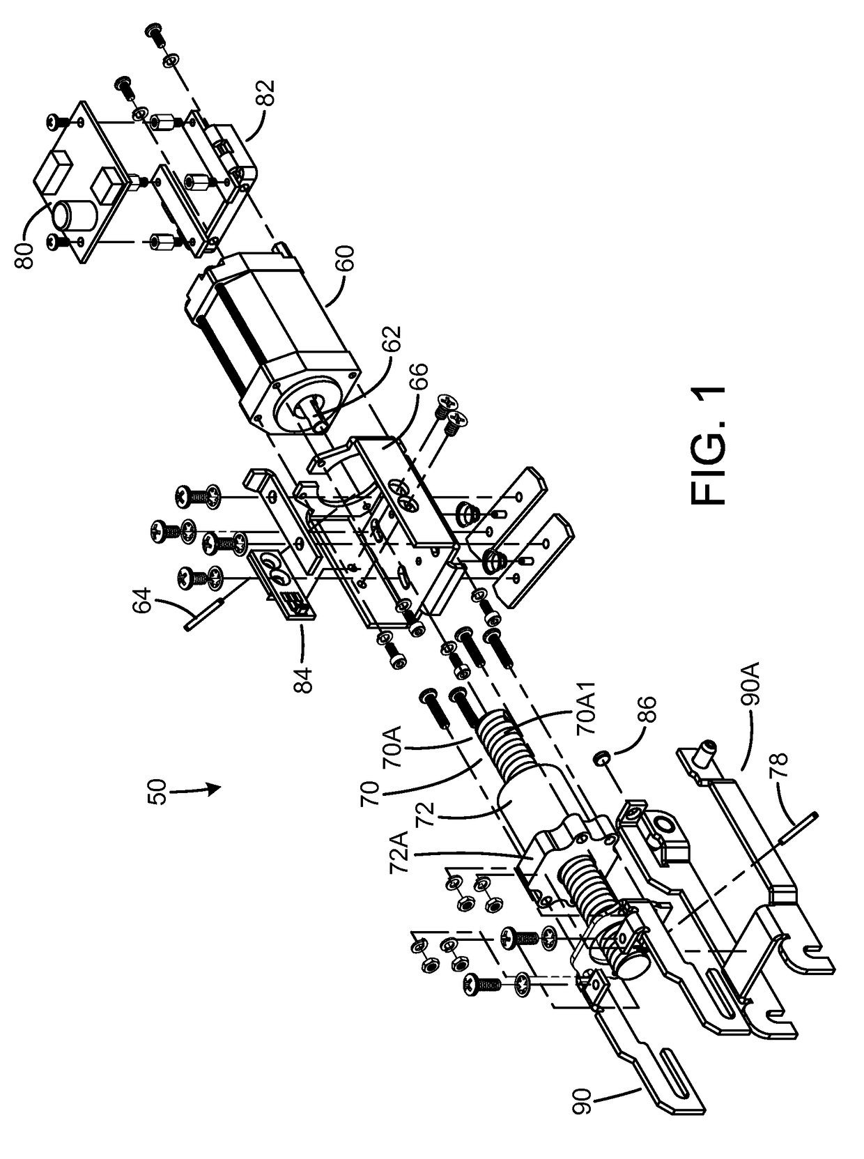
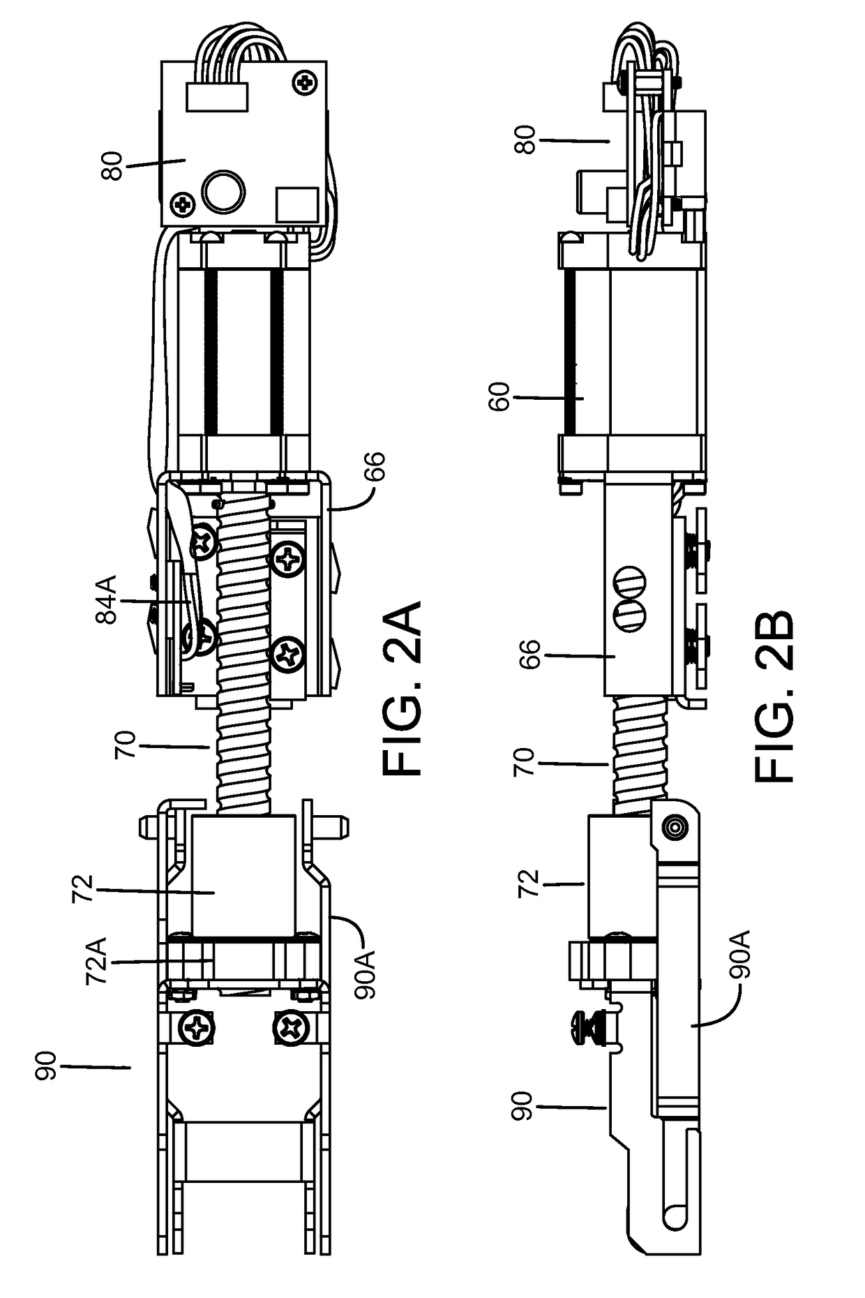
[0019]An exemplary embodiment provides an actuator using a ball screw or ball drive for converting the rotational force of a motor 60 into a linear force. With a ball screw, bearing balls are used in-between the screw and nut threads to provide a rolling transfer of the power between the two parts, significantly reducing the friction losses. Further, the frictional loses associated with back-driving a...


PUM


Abstract

An embodiment is an electromechanical door latch system including a latch device configured for motion between a latched position and an unlatched position. A manually actuated mechanical apparatus is coupled to the latch device and configured to move the latch device to the unlatched position in response to force applied by a user to a component of the mechanical apparatus. An electromechanical actuator system moves the latch device to an actuator unlatched position in response to an electrical signal from an access control device. The electromechanical actuator system includes a control module, a motor, and a ball screw drive including a ball screw or threaded nut, with one coupled to the motor shaft and the other configured for connection to a latch mechanism, and at least one recirculating ball circuit including ball bearings for transferring torque from the motor to the ball screw drive.

Description

BACKGROUND[0001]Push bar exit devices are mounted on the egress side of the door. They can be mounted for rim, mortise, surface vertical rods, or concealed vertical rods applications. Push bar exit devices feature an enclosed mechanism case with a push bar area to allow egress. Some electrified latch pullback mechanisms for exit devices allows for remote keyless access control where exit devices are used or required. Common applications include conditions such as hospitals, airports, schools, churches and they are commonly specified in applications that require automatic door openers. The device may be continuously energized allowing for a push / pull condition if desired.[0002]Electrified latch pullback modifications are a common product within the industry. They are typically solenoid or motor driven devices. Motor driven devices are usually coupled to an acme style threaded leadscrew combination to translate the rotational output force of the motor to the linear force most commonly...

Claims


Application Information

Patent Timeline
Patent Type & Authority Applications(United States)
IPC IPC(8): F16H25/22
CPCF16H25/2214F16H25/2228E05B47/0012E05B47/023E05B65/1053E05B2047/0023E05B2047/0091
Inventor STEPHENSON, JEFFREY J.
Owner COMMAND ACCESS TECH INC
Why Eureka
Try Eureka