
Modular flush-mount sign channel track system and method

a technology of sign channel and track system, which is applied in the field of system and method for mounting signs, can solve the problems of time-consuming and expensive production of specific design multiple track sign board, high cost of shipping of large sign board, and increased risk of damage to large sign board, so as to reduce the risk of damage, less expensive to ship, and the effect of quick and easy to form

Active Publication Date: 2017-04-13
K INT
View PDF1 Cites 2 Cited by
  • Summary
  • Abstract
  • Description
  • Claims
  • Application Information

AI Technical Summary

Benefits of technology

The patent text describes a modular sign board system that can be separated into smaller panels for easier and less expensive installation. These panels can be assembled, reconfigured and customized at the store location, replacing multiple single configuration sign boards. The system can be mounted using an offset ladderless mounting apparatus, which allows the sign to be mounted flush and tight to the ceiling, maximizing the surface area while still providing head room for customers and preventing shoplifting. The system is safer, easier to install and remove, and can replace multiple signs with a single mounting pole.

Problems solved by technology

As a result, the specifically designed multiple track sign board may be time consuming and expensive to produce.
Multiple track sign boards are large, the result of which is that shipping of the large sign boards may be expensive.
The large sign boards are also more prone to damage during shipping.
A large multiple track sign board occupies a significant amount of space when stored.
It is also prone to damage during storage due to its large size.
If the store has a sign board having, for example, two channel tracks for strip signs and one channel track for spiral bound number sets, it will not be possible for the store to use the sign board to hold two or three different prices using spiral bound number sets.
Store personnel may find that unfortunately the sign board that the store has available for use may fail to meet the immediate need.

Method used


Image

  • Modular flush-mount sign channel track system and method
  • Modular flush-mount sign channel track system and method
  • Modular flush-mount sign channel track system and method

Examples


Embodiment Construction

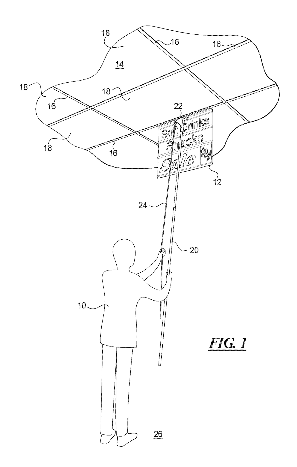
[0028]In FIG. 1, a person 10 is mounting or unmounting a sign 12 at a ceiling 14. The sign 12 is being connected to or removed from a grid member 16. The grid member 16 is one of several grid members 16 that hold ceiling tiles 18. The grid member 16 is magnetically attractive, such as being formed of a ferromagnetic material, so that a magnet may attach to the grid member 16. To mount or unmount the sign 12 at the ceiling 14 without using a ladder or other object to climb on, the user 10 is holding a pole 20 that has a gripper 22 at the end. The gripper 22 holds the sign 12 as the user moves the sign 12 to a position at the ceiling 14. The gripper 22 includes a rope or cord 24 that extends from the gripper 22 to a position where the person 10 may pull on the rope or cord 24 to release the gripper 22 from the sign 12 when at the mounting position. The sign is positioned at and mounted to the grid member 16 while the person's feet remain on the floor 26. This may be accomplished regar...


PUM


Abstract

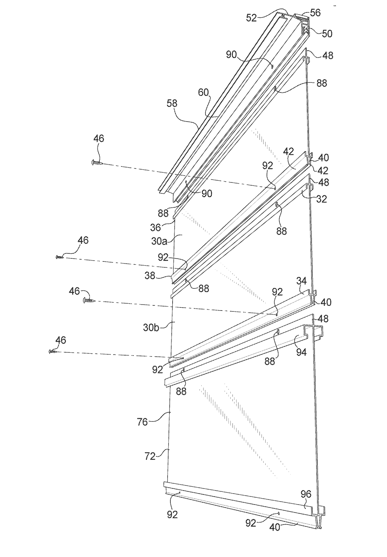
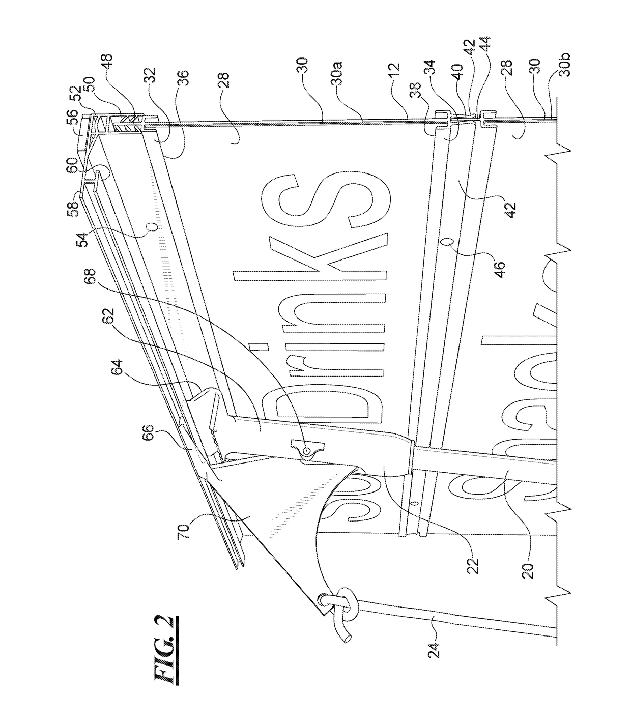
A system and method for magnetically mounting a sign flush at a ceiling, window, or wall location that includes modular panels that are removably connected to one another to form a sign board stack. The sign board stack is mounted or unmounted from a prominent display location using a pole end gripper without the need for a ladder. The sign stack extends from a mounting strip having a holder at which the sign stack is fastened, and the gripper engages the mounting strip at an offset grasping portion disposed laterally of the holder. The panels have flanges at the top edge to fit into the holder of the mounting strip and clips at the bottom edge to hold a flange of a panel connected below it. Channel tracks are formed on the panels to hold strip sign elements, some of which may include accordion or spiral bound numbers or messages.

Description

BACKGROUND OF THE INVENTION[0001]Field of the Invention[0002]The present invention relates generally to a sign holder for interchangeable signs, and more particularly to a system and method for mounting signs that include interchangeable signs held in tracks or channels.[0003]Description of the Related Art[0004]Convenience stores, gas stations, markets, grocery stores, and other types of stores and shops may use signs that have interchangeable sign elements. One type of sign has a sign board on which are formed channels or tracks into which sign elements are inserted. A common sign element is a strip of cardboard, plastic or other material which has been printed with the desired text and image. The strip sign element is mounted on the sign board by sliding the strip sign element into the track or channel. Sign boards are provided that accept one, two, three, or more of the strip sign elements. The sign boards may have tracks or channels on one or both sides so that the strip sign el...

Claims


Application Information

Patent Timeline
Patent Type & Authority Applications(United States)
IPC IPC(8): G09F7/18B25J1/04F16M13/02
CPCG09F7/18F16M13/027B25J1/04F16B2001/0035G09F2007/1852G09F2007/186G09F2007/1847G09F7/10
Inventor WHITE, MICHAEL J.
Owner K INT
Learn More