Hybrid security device for security document or token

a security document and hybrid technology, applied in the security field, can solve the problems of reducing the resolution or accuracy of the microstructure formed, the depth of the required etching, and the loss of accuracy of the etching process

Inactive Publication Date: 2017-04-20
CCL SECURE PTY LTD
View PDF1 Cites 10 Cited by
  • Summary
  • Abstract
  • Description
  • Claims
  • Application Information

AI Technical Summary

Benefits of technology

[0096]The invention provides a commercially practical hybrid security device with two different sets of microstructures having significantly different heights in very close proximity to each other, or even one inter-mingled within the other. Normally the originating master for producing these security devices uses a positive photoresist because the resulting structure is generally more robust as the bulk of the unexposed resist provides reinforcement to hold the pattern together. However, the present invention is based on the realisation that microstructures with significantly different heights can be simultaneously formed together on an originating master in a process that is relatively time efficient. Using a negative photoresist exposed to electron beam writing avoids need to use masking while the microstructures are accurately built up layer by layer. Alternatively, the originating master is formed from successive reactive ion etches into a glass substrate which is used to make a metal shim. It will be appreciated that this is fundamentally different from forming structures by deep etch removal of material that is not part of the structure thereby avoiding any problems with ‘proximity effects’.

Problems solved by technology

If the height profile difference between various features in the microstructure is significant, the required etch depth becomes large and the etch process loses accuracy.
This causes chemical crosslinking in areas that are not meant to be removed by the etchant which reduces the resolution or accuracy of the microstructures formed.
Of course, this technique greatly increases the time and complexity of the process.
A security device with a diffraction grating immediately adjacent a hologram or perhaps completely surrounding a hologram (or vice versa) will provide a highly distinctive visual impression, as well as being exceptionally difficult for counterfeiters to replicate.

Method used


Image

  • Hybrid security device for security document or token
  • Hybrid security device for security document or token
  • Hybrid security device for security document or token

Examples


Embodiment Construction

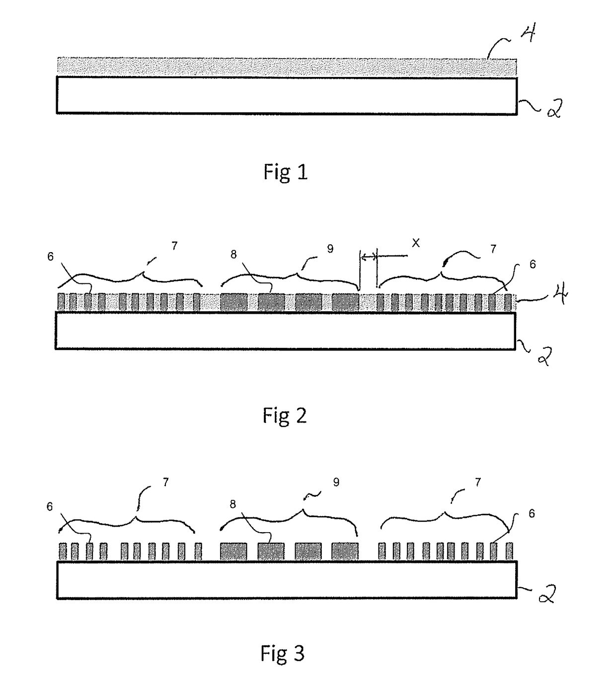
[0117]FIG. 1 shows the first step of producing the originating master which is used to create a metal shim that in turn embosses the security devices. A supporting plate 2 has a layer of negative photoresist 4 spun on to a depth of 0.5 microns.

[0118]FIG. 2 shows the first layer of negative photoresist 4 after an electron beam has written the first stages of the first and second micropatterns (6 and 8 respectively) within first and second regions (7 and 9 respectively). As the first and second microstructures (6 and 8) are being formed in the same lithographic process, the first and second regions (7 and 9) can be positioned closely adjacent, or even intermingled within one another. The spacing between the first and second microstructures ‘X’ is less than 5 mm and typically less than 1 mm.

[0119]The first and second regions intermingle with each other in one or more areas on the plate. The regions may be interlaced such that strips of the first microstructure are interleaved with stri...


PUM

PropertyMeasurementUnit
heightaaaaaaaaaa
widthaaaaaaaaaa
viscosityaaaaaaaaaa

Abstract

A hybrid security device for security documents and the like, with the microstructure for a first optically variable device (OVD) and the microstructure for a second OVD mutually interlace or interspersed. The first microstructure has a height profile that differs from that of the second microstructure by more than 0.5 microns. Suitable fabrication processes for the hybrid security device are also disclosed.

Description

FIELD OF THE INVENTION[0001]The invention relates to security devices applied to security documents or tokens as a counterfeit deterrent. The invention also relates to production methods used for manufacturing these security devices and subsequently applying them to security documents or tokens.DEFINITIONS[0002]Security Document or Token[0003]As used herein the term security documents and tokens includes all types of documents and tokens of value and identification documents including, but not limited to the following: items of currency such as banknotes and coins, credit cards, cheques, passports, identity cards, securities and share certificates, driver's licenses, deeds of title, travel documents such as airline and train tickets, entrance cards and tickets, birth, death and marriage certificates, and academic transcripts.[0004]The invention is particularly, but not exclusively, applicable to security documents or tokens such as banknotes or identification documents such as ident...

Claims


Application Information

Patent Timeline
Patent Type & Authority Applications(United States)
IPC IPC(8): B42D25/328B42D25/42G02B5/18B42D25/21G03F7/00B42D25/324B42D25/425
CPCB42D25/328B42D25/324B42D25/42G02B5/1857B42D25/21G03F7/0035B42D25/425G03F7/2059
Inventor LEE, ROBERT ARTHURHARDWICK, MICHAEL
Owner CCL SECURE PTY LTD
Why Eureka
Try Eureka