Air conditioning device for vehicle
- Summary
- Abstract
- Description
- Claims
- Application Information
AI Technical Summary
Benefits of technology
Problems solved by technology
Method used
Image
Examples
first embodiment
Second Variation of First Embodiment
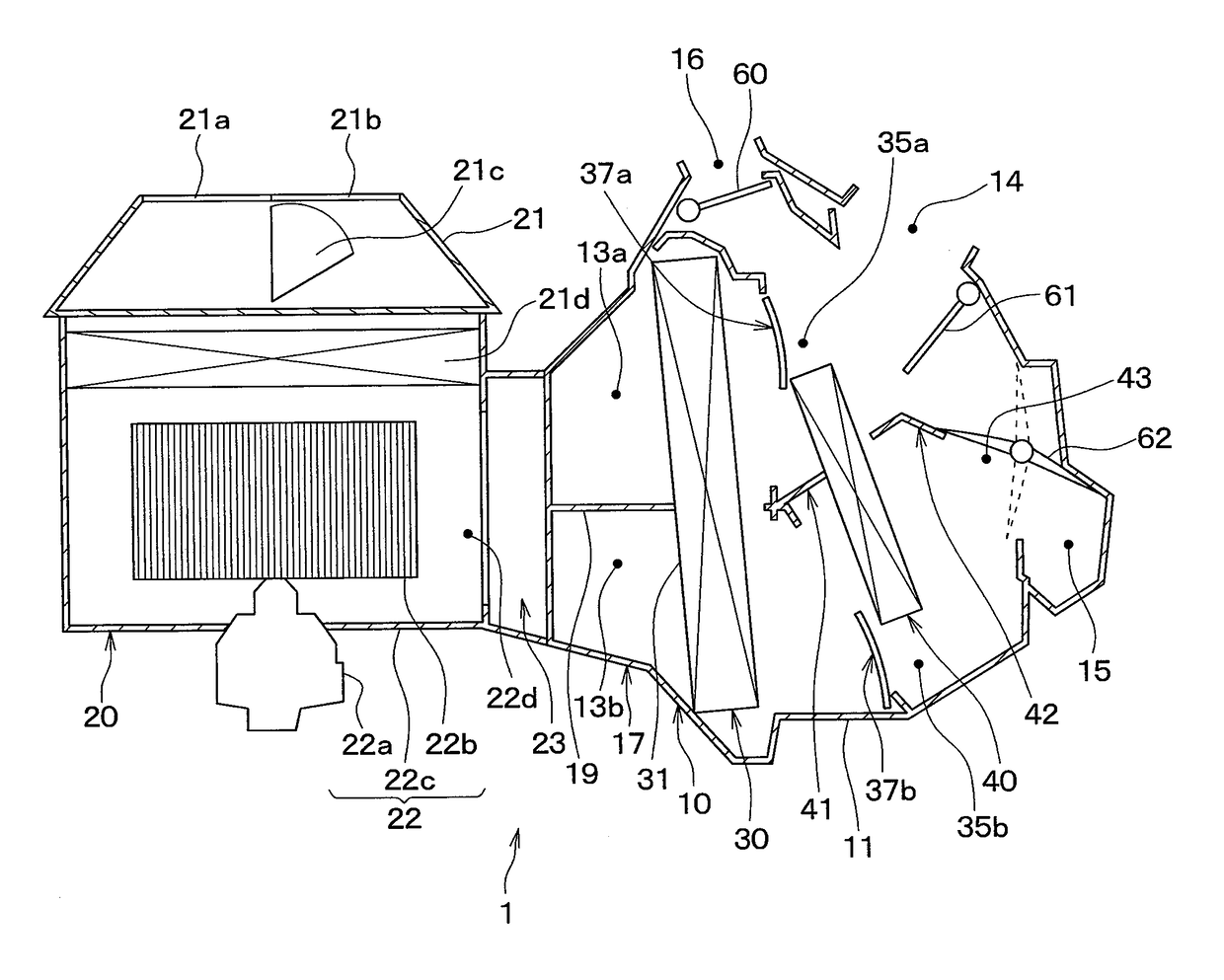
[0098]According to the present variation, the airflow adjustment case portion 17 of the above-described first embodiment is provided with air passages 70a, 70b through which air flows between the upper ventilation path 13a and the lower ventilation path 13b as shown in FIG. 7.
[0099]The airflow adjustment case portion 17 of the present variation has a protruding portion 19X such that a center portion of the partition wall 19 in the vehicle width direction protrudes toward the cooling heat exchanger 30. In addition, recessed portions 19Y, 19Z are provided in the partition wall 19 on one side and the other side of the protruding portion 19X in the vehicle width direction respectively. Each of the recessed portions 19Y, 19Z is recessed toward an opposite side from the cooling heat exchanger 30. In other words, the recessed portions 19Y, 19Z are recessed away from the cooling heat exchanger 30. Thus, the air passage 70a is formed between the air inflow...
second embodiment
First Variation of Second Embodiment
[0110]According to the second embodiment, the airflow adjustment case portion 17 is not provided with the air passages 70a, 70b. However, as shown in FIG. 10, the airflow adjustment case portion 17 may be provided with air passages 70a, 70b.
[0111]As shown in FIG. 10, the plate members 19a, 19b, 19c of the present variation are arranged to be distanced from each other in the vehicle width direction. The air passage 70a is formed on a side of the plate member 19a adjacent to the cooling heat exchanger 30, in other words, between the plate member 19a and the cooling heat exchanger 30. The air passage 70b is formed on a side of the plate member 19c adjacent to the cooling heat exchanger 30, in other words, between the plate member 19c and the cooling heat exchanger 30.
[0112]According to the present variation, a depth dimension of the plate member 19b is greater than depth dimensions of the plate members 19a, 19c. Therefore, the plate member 19b has a...
third embodiment
Fourth Variation of Third Embodiment
[0130]According to a fourth variation, similar to the second variation of the first embodiment, air passages 70a, 70b may be further formed between the air inflow surface 31 of the cooling heat exchanger 30 and each of the lower wall 81a and the upper wall 80 as shown in FIGS. 17 and 18, as compared to the third variation of the third embodiment. In this way, effects similar to those of the second variation of the first embodiment can be obtained.
Fourth Embodiment
[0131]According to the present embodiment, the airflow adjustment case portion 17 further has two partition walls as compared to the above-described third embodiment. FIG. 19 is a schematic diagram illustrating an inside of the airflow adjustment case portion 17 of the present embodiment.
[0132]The airflow adjustment case portion 17 of the present embodiment further has partition walls 84a, 84b as compared to the airflow adjustment case portion 17 shown in FIG. 16. The partition wall 84a i...
PUM
 Abstract
Description
Claims
Application Information
 - R&D
- Intellectual Property
- Life Sciences
- Materials
- Tech Scout
- Unparalleled Data Quality
- Higher Quality Content
- 60% Fewer Hallucinations
Browse by: Latest US Patents, China's latest patents, Technical Efficacy Thesaurus, Application Domain, Technology Topic, Popular Technical Reports.
© 2025 PatSnap. All rights reserved.Legal|Privacy policy|Modern Slavery Act Transparency Statement|Sitemap|About US| Contact US: help@patsnap.com


