External power supply apparatus and vehicle power supply method

a technology for external power supply and power supply circuit, which is applied in the direction of electric vehicles, single contact parts, vehicle components, etc., can solve the problems of inrush current (pulse current) to be generated, damage to power reception circuitry, and complex configuration of power reception circuitry, etc., to achieve easy stabilization, easy stabilization, and steep voltage fluctuation

Active Publication Date: 2017-04-20
HONDA MOTOR CO LTD
View PDF1 Cites 8 Cited by
  • Summary
  • Abstract
  • Description
  • Claims
  • Application Information

AI Technical Summary

Benefits of technology

[0014]According to the above, the power receiving device of the electric vehicle comes into contact with the power lines after being guided by the guide member. Owing thereto, in comparison with a case in which the power receiving device contacts the power lines without the guide member, the behavior of the power receiving device at the time that contact with the power lines is started is easily stabilized. Therefore, a steep voltage fluctuation accompanying separation of the power receiving device from the power lines and recontact therewith after initial contact with the power lines is started can be suppressed. Consequently, supply of power to the electric vehicle from the external power supplying apparatus can stably be carried out.
[0015]The guide member may be bent so that a facing distance in the vehicle transverse direction between the guide member and a side cart of the electric vehicle narrows along the direction of travel. Owing thereto, a pressing force from the power receiving device to the guide member is easily increased as the electric vehicle progresses. For this reason, when the power receiving device contacts the power lines, it is possible to adjust the pressing force on the power lines from the power receiving device so as to be comparatively high. Consequently, the behavior of the power receiving device at the time that contact with the power lines is started is easily stabilized.

Problems solved by technology

In this case, it is likely for an inrush current (pulse current) to be generated, with the concern that damage may occur to the power reception circuitry of the electric vehicle 10.
Further, if a circuit component for the purpose of avoiding generation of the aforementioned inrush current is provided in the power reception circuitry, the configuration of the power reception circuitry becomes complex.
Such a problem occurs not only in the case of a contact-type power supplying method, but also occurs in the case of a contactless power supplying (wireless power supplying) method.

Method used


Image

  • External power supply apparatus and vehicle power supply method
  • External power supply apparatus and vehicle power supply method
  • External power supply apparatus and vehicle power supply method

Examples


embodiment

I. Embodiment

1A. Configuration

[1A-1. Overall Configuration]

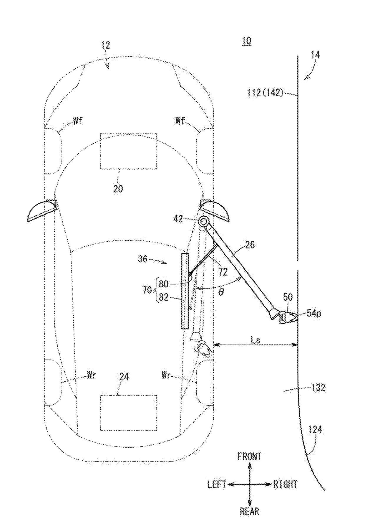
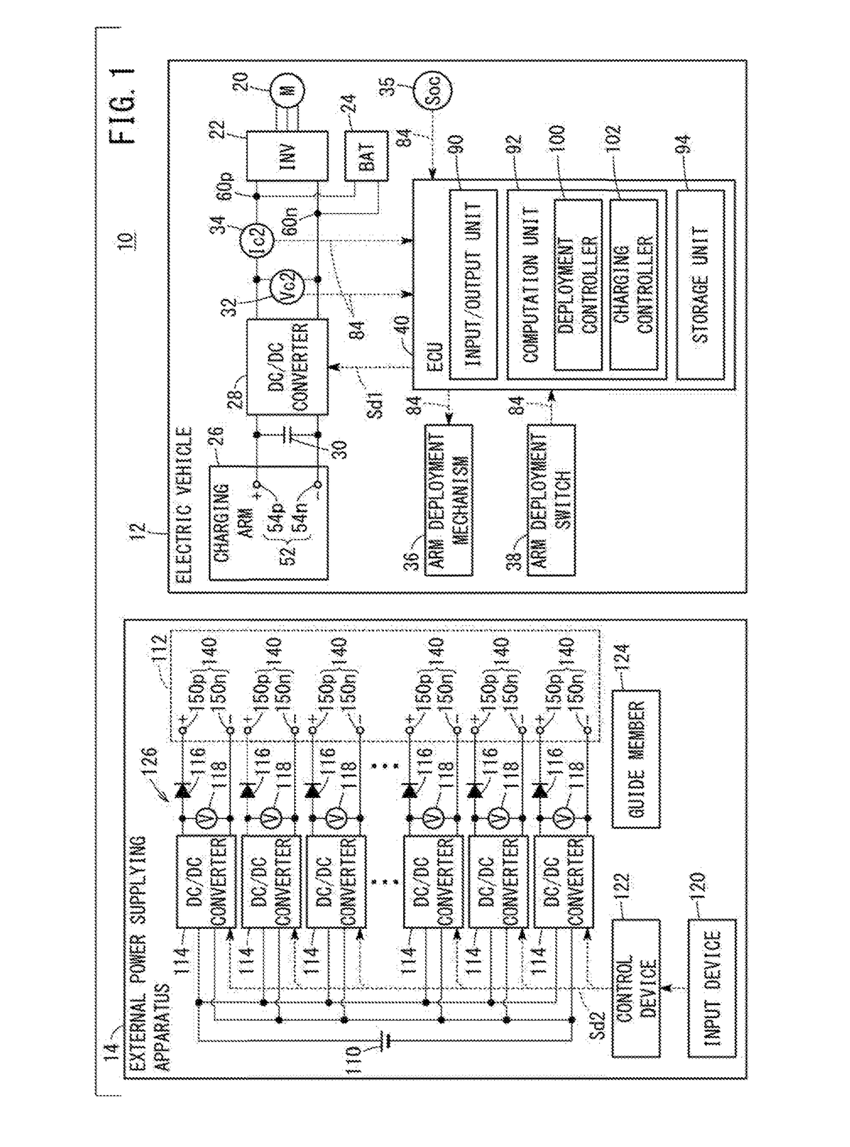
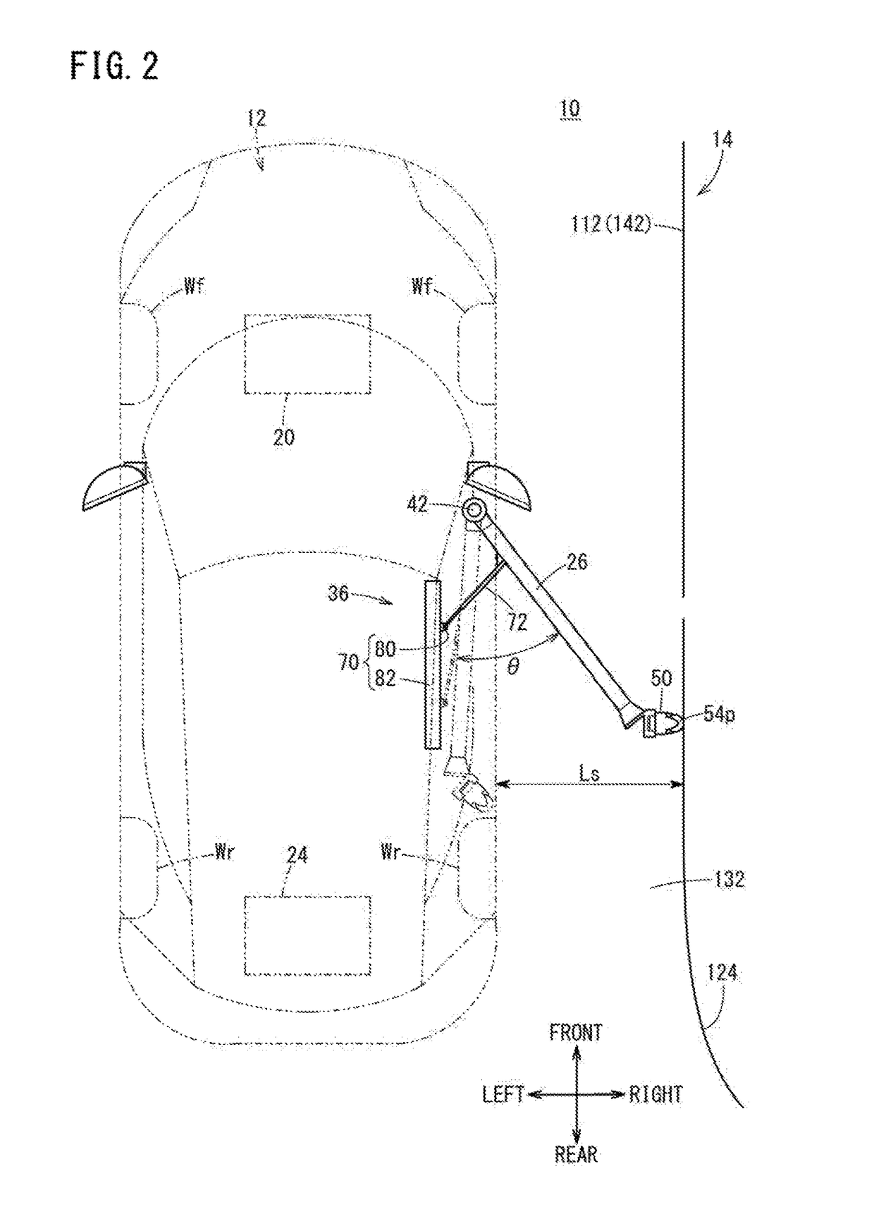
[0028]FIG. 1 is an outline schematic view of a charging system 10 including an external power supplying apparatus 14 according to an embodiment of the present invention. FIG. 2 is a plan view showing with emphasis portions of the charging system 10. FIG. 3 is a front view showing with emphasis portions of the charging system 10. As shown in FIGS. 1 through 3, the charging system 10, in addition to the external power supplying apparatus 14 (hereinafter also referred to as a “power supplying apparatus 14”), includes an electric vehicle 12 (hereinafter also referred to as a “vehicle 12”). Any of the directions (“front”, “rear”, “left”, “right”, “up”, “down”) in FIGS. 2 and 3 are directions on the basis of the vehicle 12 (the same holds true for FIGS. 4 and 5).

[0029]According to the present embodiment, electrical power is supplied to the vehicle 12 from the power supplying apparatus 14, and charging of a battery 24 (see FIG. 1) ...


PUM


Abstract

Provided are an external power supply apparatus and a vehicle power supply method, whereby a power reception circuit of an electric vehicle can be projected or a configuration of the electric vehicle can be simplified. An external power supply apparatus is provided with a power supply unit, which is provided along a traveling path, and which supplies power to a power reception unit of an electric vehicle while the vehicle is traveling; and a voltage applying unit that applies a voltage to the power supply unit. The power supply unit includes a plurality of divided power supply units that are divided along the traveling path. The voltage applying unit applies the voltage such that the voltage to be applied to the divided power supply units becomes higher in the traveling direction of the electric vehicle.

Description

TECHNICAL FIELD[0001]The present invention relates to an external power supplying apparatus and a vehicle power supplying method for supplying electrical power to a vehicle during traveling.BACKGROUND ART[0002]As disclosed in Japanese Laid-Open Patent Publication No. 2013-233037 (hereinafter referred to as JP 2013-233037A), during traveling of an electric vehicle 10, a charging arm 18 is extended out in a vehicle transverse direction, and charging from a power supplying apparatus 26 is carried out by bringing the charging arm 18 into contact with power lines 24 made up from a positive electric power line 24p and a negative electrode power line 24n (see Abstract). A direct current or an alternating current high voltage is applied to the power lines 24 from a non-illustrated external power source (paragraph [0023]).SUMMARY OF INVENTION[0003]As noted above, according to JP 2013-233037A, a direct current or an alternating current high voltage is applied to the power lines 24 from the no...

Claims


Application Information

Patent Timeline
Patent Type & Authority Applications(United States)
IPC IPC(8): B60M1/36B60L5/40
CPCB60L5/40B60M1/36B60L5/36B60L5/42B60M1/30
Inventor TAJIMA, TAKAMITSUSHIBAHATA, YASUJINOGUCHI, WATARUARUGA, TOMOHISA
Owner HONDA MOTOR CO LTD
Why Eureka
Try Eureka