
Electric bicycle transmission systems, methods, and devices

Active Publication Date: 2017-04-20
CIVILIZED CYCLES INC
View PDF5 Cites 41 Cited by
  • Summary
  • Abstract
  • Description
  • Claims
  • Application Information

AI Technical Summary

Benefits of technology

The patent is about an electric bicycle that has a special transmission system that automatically selects and shifts gears based on the current conditions and without user input. This system allows for smoother shifting during stops or when the rider is not using the bicycle. The electric bicycle can also adapt to different parts and configurations, such as motors and batteries. The transmission is controlled by monitoring the speed of the wheel and reducing the speed of the sprocket set during shifts to maintain the wheel's speed. The wheel can be connected to the sprocket set through a one-way freewheel clutch or an active clutch that allows for smoother shifting while the bicycle is stopped or rotating at a slower speed. The electric bicycle can also be controlled based on different modes, such as bicycle mode, moped mode, or off-road-only mode, to provide different levels of performance.

Problems solved by technology

One challenge with bicycles is that it can be easier or harder to pedal the bicycle depending on various factors, such as speed, inclination, rider ability, and the like.
Most electric bicycles are quite particular and lack compatibility or flexibility.
In other words, the electric bicycle industry lacks any standard or base model that can easily be adapted to accommodate different regulations, different parts, and / or different configurations.

Method used


Image

  • Electric bicycle transmission systems, methods, and devices
  • Electric bicycle transmission systems, methods, and devices
  • Electric bicycle transmission systems, methods, and devices

Examples


Embodiment Construction

[0055]Embodiments will now be described with reference to the accompanying figures. The terminology used in the description presented herein is not intended to be interpreted in any limited or restrictive manner, simply because it is being utilized in conjunction with a detailed description of certain specific embodiments. Furthermore, embodiments may comprise several novel features, no single one of which is solely responsible for its desirable attributes or which is essential to practicing the embodiments herein described.

[0056]The disclosure herein provides systems, methods, and devices that enable various forms of automatic transmission systems and automatic transmission control methods for electrically powered bicycles. Bicycles, manual or electric, often comprise some form of gear shifting mechanism that enables a gear ratio between a pedal crank and a drive wheel to be varied. For example, in a road bicycle, a pedal crank is coupled to one or more drive sprockets, and a drive...


PUM


Abstract

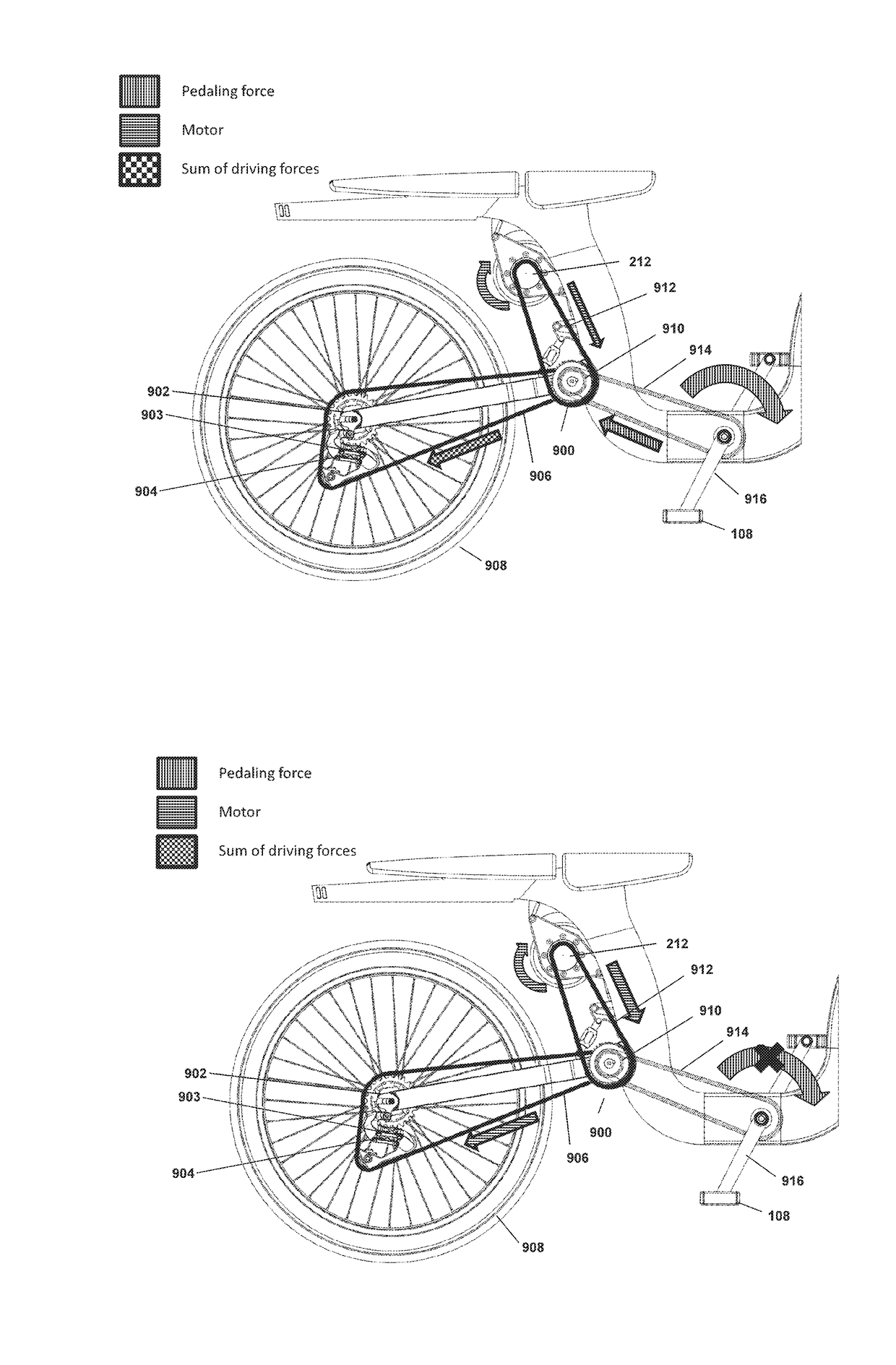
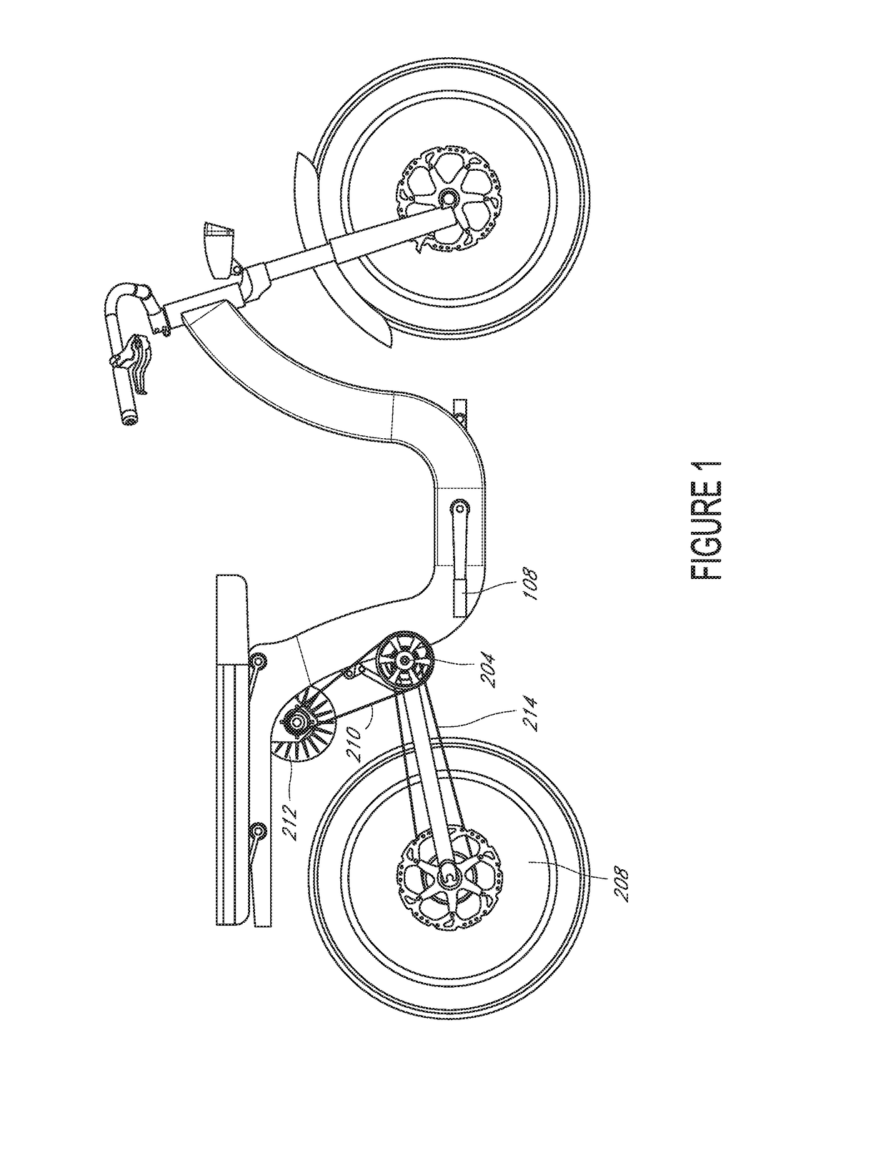
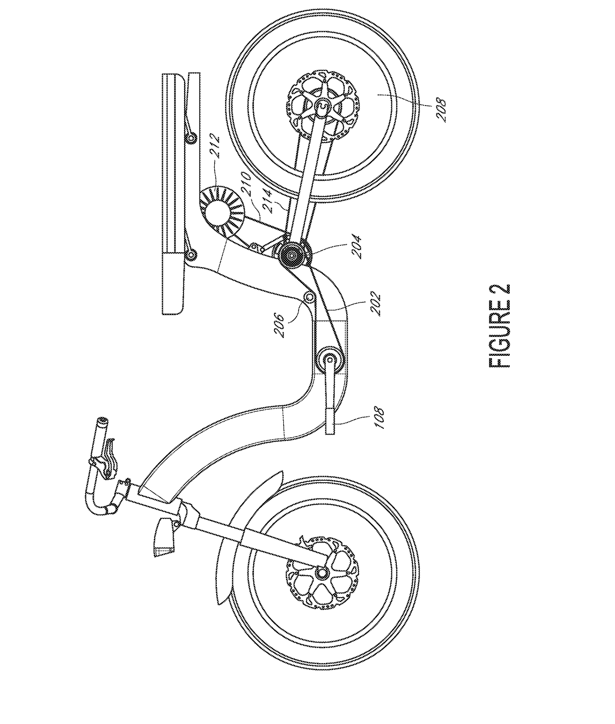
A derailleur-based electronic transmission system for an electric bicycle comprises a wheel; a driven sprocket set coupled to the wheel via at least a first one-way clutch, the driven sprocket set comprising two or more concentric sprockets of different effective diameters; a drive chain configured to engage the driven sprocket set; an electronically controllable derailleur configured to move the drive chain among the two or more sprockets; a pedal crank configured to cause rotation of the driven sprocket set by providing a user pedal force to the driven sprocket set through at least a second one-way clutch and the drive chain; a motor configured to cause rotation of the driven sprocket set by providing an electromechanical force to the driven sprocket set through at least a the drive chain; and an electronic controller configured to, responsive to a determination that a shift should occur at a time when neither the pedal crank nor the motor is causing rotation of the driven sprocket: operate the motor to rotate the driven sprocket at a rotational speed less than or equal to a current rotational speed of the wheel; and operate the derailleur to cause the shift to occur while the driven sprocket is being rotated by the motor.

Description

CROSS-REFERENCE TO RELATED APPLICATIONS[0001]This application claims the benefit of U.S. Provisional Patent Application No. 62 / 115,800, titled ELECTRIC BICYCLE TRANSMISSION SYSTEMS, METHODS, AND DEVICES, filed Feb. 13, 2015, which is hereby incorporated by reference herein in its entirety.BACKGROUND[0002]Field[0003]Embodiments relate to the field of bicycles, and, in particular, to transmissions for electric bicycles.[0004]Description[0005]Bicycles enable a rider to transport himself or herself over a riding surface by converting a pedaling motion of the rider's legs into rotational motion of a drive wheel of the bicycle. One challenge with bicycles is that it can be easier or harder to pedal the bicycle depending on various factors, such as speed, inclination, rider ability, and the like. To enable easier pedaling and / or to make riding a bicycle more efficient, various devices have been developed to enable selectively changing a gear ratio between a pedal crank and the drive wheel....

Claims


Application Information

Patent Timeline
IPC IPC(8): B60W30/18F16D41/24B62J99/00B62M25/08B60W10/08B60W10/11B62M9/04B62M6/45
CPCB60W30/181B62M9/04F16D41/24B62M6/45B62M25/08B60W10/08B62J2099/0013B62J99/00B60W2510/104B60W2520/28B60W2710/081B60W2710/1005B60W2710/1038B60W10/11B62M6/40B62M9/06B62J43/13B62J45/20B62J50/22F16H7/06B62M9/122B62M9/132Y02T10/72
Inventor SCHIEFFELIN, ZACHARY
Owner CIVILIZED CYCLES INC
Learn More