Noise reduction device for negative pressure line of brake booster

a technology of negative pressure line and noise reduction device, which is applied in the direction of braking system, functional valve type, braking components, etc., can solve the problems of increasing the cost of the vehicle, reducing the service life of the booster, and not always constant generation of negative pressure, so as to reduce noise, prevent the effect of reducing the charging speed of negative pressur

Active Publication Date: 2017-04-27
HYUNDAI MOTOR CO LTD +1
View PDF3 Cites 2 Cited by
  • Summary
  • Abstract
  • Description
  • Claims
  • Application Information

AI Technical Summary

Benefits of technology

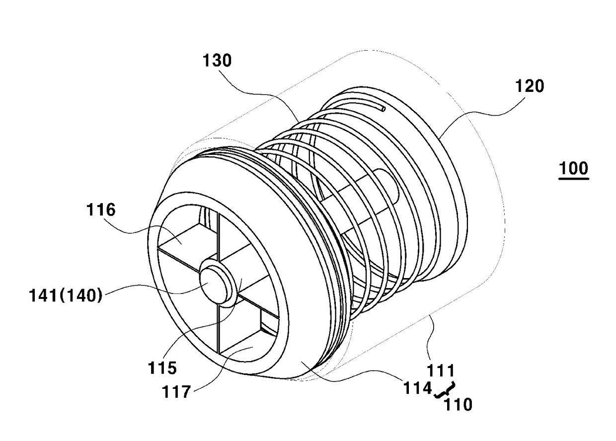
[0014]The present invention provides an improved noise reduction device which is disposed in a vacuum hose. Namely, a negative pressure line of a vehicle connects a brake booster and a surge tank of an engine via the vacuum hose to use negative pressure of the surge tank, and reduces noise caused by pulsation of an air flow and vibration of a valve which occur due to an operation of an engine piston. In particular, a noise reduction device which has a reduced geometry (e.g., size) may be more easily disposed within a vacuum hose and may improve a negative pressure charging speed.
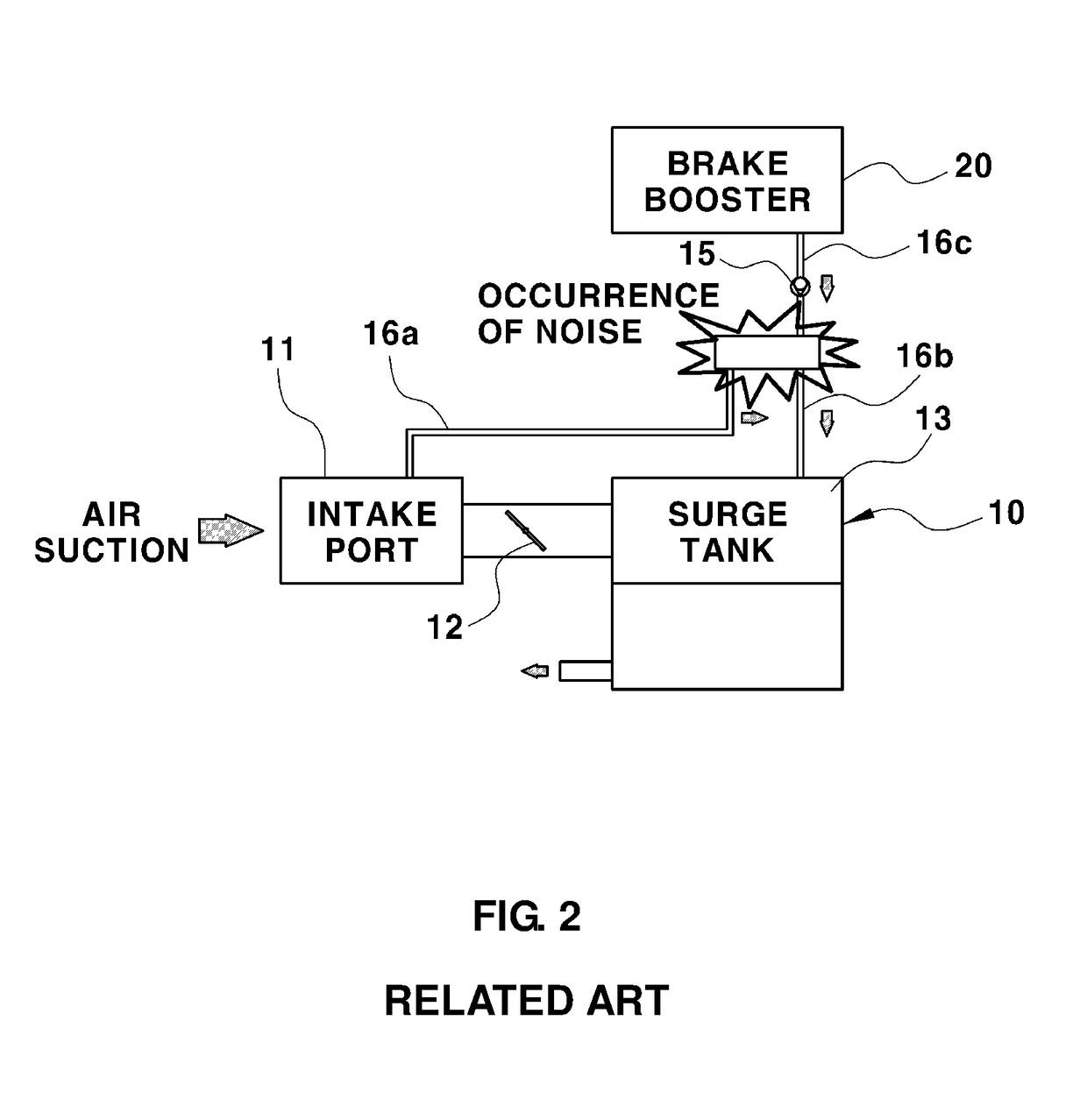
[0024]The noise reduction device may have a reduced size, and may be installed by being simply inserted into the vacuum hose, and as a result, the noise reduction device may be more easily installed. Furthermore, it is not necessary to separate the negative pressure line (vacuum hose) at an installation position like the related art, and components such as a fixing clip may be omitted. As a result, it may be possible to reduce costs, and solve a problem regarding a restriction on installation caused by a layout condition at the periphery of the vacuum hose.

Problems solved by technology

For example, when the vacuum pump is used, the necessity of a separate device causes an increase in costs of the vehicle.
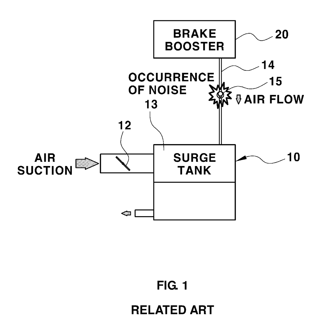
However, when negative pressure generated in the surge tank of the engine is used, the negative pressure is not always constantly generated.
In particular, the negative pressure changes based on an ambient environment such as a mountainous area where air density is low, and as a result, the availability of the negative pressure required for the booster cannot be always ensured.
Further, noise occurs due to resonance caused by the pulsation and vibration.
Namely, air flow noise occurs due to air vibration in the vacuum hose and vibration of the check valve in the negative pressure intensifier.

Method used


Image

  • Noise reduction device for negative pressure line of brake booster
  • Noise reduction device for negative pressure line of brake booster
  • Noise reduction device for negative pressure line of brake booster

Examples


Embodiment Construction

[0074]Hereinafter reference will now be made in detail to various exemplary embodiments of the present invention, examples of which are illustrated in the accompanying drawings and described below. While the invention will be described in conjunction with exemplary embodiments, it will be understood that the present description is not intended to limit the invention to those exemplary embodiments. On the contrary, the invention is intended to cover not only the exemplary embodiments, but also various alternatives, modifications, equivalents and other exemplary embodiments, which may be included within the spirit and scope of the invention as defined by the appended claims.

[0075]It is understood that the term “vehicle” or “vehicular” or other similar term as used herein is inclusive of motor vehicles in general such as passenger automobiles including sports utility vehicles (SUV), buses, trucks, various commercial vehicles, watercraft including a variety of boats and ships, aircraft,...


PUM


Abstract

A noise reduction device for a negative pressure line of a brake booster is provided. The improved noise reduction device is disposed in a vacuum hose, and includes a negative pressure line of a vehicle in which a brake booster and a surge tank of an engine are connected via the vacuum hose to use negative pressure of the surge tank. In particular, noise caused by pulsation of an air flow and vibration of a valve which occur due to an operation of an engine piston is reduced.

Description

CROSS-REFERENCE TO RELATED APPLICATION[0001]This application claims under 35 U.S.C. §119(a) the benefit of Korean Patent Application No. 10-2015-0148462 filed on Oct. 26, 2015, the entire contents of which are incorporated herein by reference.BACKGROUND[0002](a) Technical Field[0003]The present disclosure relates to a noise reduction device for a negative pressure line of a brake booster, and more particularly, to a noise reduction device which is disposed in a vacuum hose. In particular, a negative pressure line of a vehicle in which a brake booster and a surge tank of an engine are connected via the vacuum hose to use negative pressure of the surge tank, and reduce noise caused by pulsation of an air flow and vibration of a valve caused by an operation of an engine piston.[0004](b) Background Art[0005]Generally, as vehicle size increases and a speed of the vehicle increases, a brake booster is used secure the brake function of the vehicle with minimal force exerted on a brake peda...

Claims


Application Information

Patent Timeline
Patent Type & Authority Applications(United States)
IPC IPC(8): B60T17/00F16K15/02
CPCB60T17/008B60T13/52F16K15/025F16K15/026F16K15/063
Inventor CHAE, MIN YEONG
Owner HYUNDAI MOTOR CO LTD
Why Eureka
Try Eureka