Sensor system

a sensor and sensor technology, applied in the field of sensor systems, can solve the problems reduced measuring accuracy of sensors, and no symmetrical geometry of the lower side of the first electrode with respect to the axis of rotation, so as to reduce the danger of undesired offset signals, increase the measurement accuracy, and simple and cost-effective implementation

Inactive Publication Date: 2010-07-15
ROBERT BOSCH GMBH
View PDF2 Cites 28 Cited by
  • Summary
  • Abstract
  • Description
  • Claims
  • Application Information

AI Technical Summary

Benefits of technology

[0007]An example sensor system according to the present invention, may have the advantage that, on the one hand, the measuring accuracy is increased in a manner that is comparatively simple and cost-effective to implement, and on the other hand, the danger of undesired offset signals is reduced. In particular, the sensitivity of the example sensor system with respect to surface charges and/or with respect to mechanical stress is reduced. A reduction in the sensitivity of the sensor system with respect to surface charges is achieved in that the surface, facing the substrate, of the seismic mass is developed symmetrically with respect to the torsional axis, so that the force effects of potential differences between the side of the seismic mass facing the substrate and the substrate on both sides of the torsional axis generally compensate each other mutually. Consequently, the resulting force effect on the seismic mass is advantageously generally equal to zero, so that even in case of variation of the surface potentials as a function of the temperature and/or the service life, no undesired deflection of the seismic mass is produced. A reduction in the sensitivity of the sensor system with respect to mechanical stress is achieved in that the linking region is positioned perpendicular to the torsional axis and parallel to the main plane of extension in the vicinity of the suspension region and/or directly adjacent to the suspension region. The result is that, in response to a bending of the substrate, the geometry between the electrode and the seismic mass does not vary or varies only i

Problems solved by technology

This acceleration sensor has the disadvantage that, based on the asymmetrical mass distribution of the first electrode, the lower side of the first electrode has no symmetrical geometry with respect to the axis of rotation, compared to the upper side of the substrate.
Especially in response to a variation of these surface potentials as a function of a temperature, or as a function of the service life of the sensor, the danger exists of rocker tipping as a result of the effective force actions, and cons

Method used


Image

  • Sensor system
  • Sensor system
  • Sensor system

Examples


Embodiment Construction

[0028]In the figures, identical parts are provided with the same reference numerals and thus are usually also named or mentioned only once.

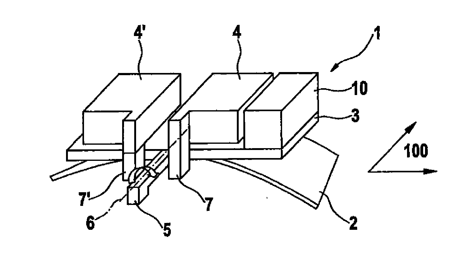
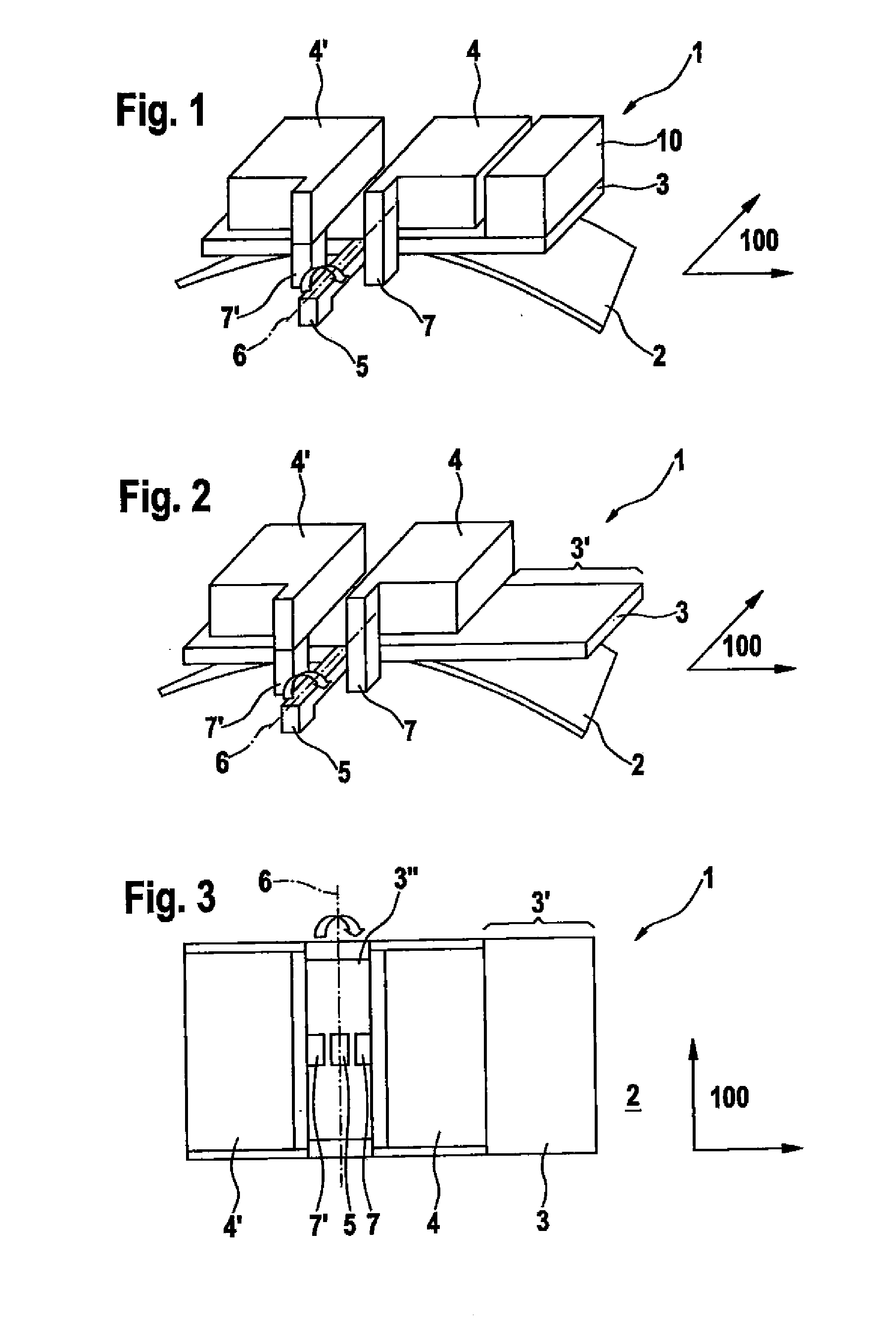
[0029]FIG. 1 shows a schematic perspective view of a sensor system 1 according to a first specific embodiment of the present invention, sensor system 1 having a substrate 2, which is represented in an exaggeratedly bent manner to illustrate the mechanical stress with respect to its main plane of extension 100. In addition, sensor system 1 includes a seismic mass 3, which is fastened in a suspension region 5 on substrate 2 in such a way that seismic mass 3 is rotatable about a torsional axis 6 relative to substrate 2, suspension region 5 especially including a bending spring and / or a torsion spring. Seismic mass 3 has a mass element 10 on one side of torsional axis 6, which produces an asymmetrical mass distribution of seismic mass 3 with respect to torsional axis 6. The result is that, when there is an acceleration of sensor system 1 perpendicula...


PUM


Abstract

A sensor system having a substrate, that has a main plane of extension, and a seismic mass, the seismic mass being developed movably about a torsional axis that is parallel to the main plane of extension; and the seismic mass having an asymmetrical mass distribution with respect to the torsional axis; and furthermore an area of the seismic mass facing the substrate is developed symmetrically with respect to the torsional axis.

Description

CROSS-REFERENCE[0001]This application claims the benefit under 35 U.S.C. §119 of German Patent Application No. DE 102009000167.0 filed on Jan. 13, 2009, which is expressly incorporated herein by reference in its entirety.FIELD OF THE INVENTION[0002]The present invention relates to a sensor system.BACKGROUND INFORMATION[0003]A sensor system is described, for instance, in European Patent No. EP 0 244 581 A1, which has a silicon chip on which, using etching technology, two equal pendulums having asymmetrically developed rotating masses, and the masses of the pendulums each being fastened to a torsion rod.[0004]A micromechanical acceleration sensor is also described in European Patent No. EP 0 773 443 A1, at least one first electrode being provided on a first semiconductor wafer to form a variable capacitance and a movable electrode in the form of an asymmetrically suspended rocker being provided on the second semiconductor wafer. Because of the asymmetrical suspension, the rocker exper...

Claims


Application Information

Patent Timeline
IPC IPC(8): G01P15/10
CPCG01P15/125G01P2015/0831
Inventor CLASSEN, JOHANNES
Owner ROBERT BOSCH GMBH
Why Eureka
Try Eureka